MSRT
The MSRT consists of the following components:
Receiver-Transmitter (RT), RT-1539. This is a very high frequency (VHF)-FM transceiver which is the heart of the MSRT. The RT-1539 is the radio used in the RAU. The radio operates in a full-duplex mode with a high and low frequency band for transmit and receive channels. In the RAU, the radio transmits in the high band and receives in the low band. This procedure reverses when the radio is used in the MSRT configuration. The RT-1539's power requirements are +21 to +33 VDC. Its levels of HF power are as follows: N0, 16W nominal; N1, 3W nominal; N2, 0.5W nominal. The continental United States (CONUS) mode is 30 to 35 MHz and 40 to 50 MHz. Outside continental United States (OCONUS) mode is 30 to 51 MHz and 59 to 88 MHz. Its radio planning range is 15 kilometers.
DSVT, TSEC/KY-68. It makes up the telephone portion of the MSRT. It functions the same as described in the previous section. The DSVT can be remoted up to one kilometer or 1/2 mile.
VHF Antenna, AS-3885. It is a fiberglass, vehicle spring-mounted whip antenna. It is insulated to avoid electrical shock. During transportation, the AS-3885 is tied down to avoid damage.
High Voltage Antenna (HVA), HVA-9. It provides high altitude electromagnetic pulse (HAEMP) protection for the MSRT and 4-wire connectivity when remoted.
Remote Power Switch. It is part of the vehicle kit. The two-position toggle switch controls power to the RT-1539 when mounted in specified Army vehicles. The remote power switch provides the power receptacle for the AN/UXC-7/7A.
MSRT AND DSVT AFFILIATION
PROCEDURES:
MSRT Affiliation RT-1539
(1) Perform all the preoperational adjustments and settings in accordance with TM 11-5820-1021-10.
(2) Turn on the radio.
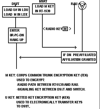
(3) Load the M key - Connect the KYK-13 to the fill connector on the front panel of the RT-1539, ensuring that the KYK-13 selector (1-6) is in the position containing the M variable and the selector switch is in the ON position. Raise the Fill/Zero switch on the RT-1539 four times in rapid succession. DO NOT RAISE MORE THAN FOUR TIMES. If the crypto alarm light goes off, the fill was successful. If the light remains lit, remove the KYK-13 and zero the RT-1539 then attempt to reload the M variable. See Figure 3-34.
Figure 3-34. MSRT affiliation process.

(4) Install the DSVT.
(5) Verify frequency plan by dialing 8 I xx R where xx is the plan number the subscriber is using. If the light comes on (you will hear either a dial or error tone), then plan xx is in reserve; if the light flashes (you will hear either a dial or error tone), then plan xx is active; if no light appears (you will hear a busy tone), then there is no plan loaded in the MSRT.
(6) Cable download--if plan xx is not loaded in the MSRT and perform the following procedures:
a. Connect frequency fill cable P2 connector to the REMOTE CONTROL CONNECTOR on the RT-1539 which is to receive the frequency plan. Connect the RT-1539 which already has the frequency plan loaded.
b. Pick up the handset on the MSRT needing the frequency plan. Unlock the DEPRESS/LOCK cradle hook switch and turn counterclockwise to the up position.
c. Using the key pad of the DSVT, dial 8CFR 8FFR.
d. You will hear a low frequency tone on the hand set and the Loaded Frequency Plan light on the RT-1539 will flash. Once this tone ceases and the Loaded Frequency Plan light goes solid, you will hear an error tone. Hang up the hand set.
e. Disconnect the fill cable from both radios.
f. Verify the frequency plan by following instructions outlined in paragraph (5) above.
(1) Place the function selector switch on the DSVT in the DSBL position. Ensure that the DSVT has been zeroized by pulling up on the VAR/STOP switch and moving it to the ZERO position and then releasing it back to the center position.
(2) Place the function selector switch on the DSVT in the LDU position. Turn on the KYK-13. Connect the KYK-13 to the DSVT and place the KYK-13 function selector switch in the position containing the U variable.
(3) Press and hold the VAR/STOP switch to the load position. A tone should be heard. Release the switch to the center position, a second tone should be heard. If the two tones were heard, the load was successful.
(4) While the KYK-13 is still connected to the DSVT, place the switch of the KYK-13 to the position containing the U variable. Place the DSVT selector switch to the LDX position. Press and hold the VAR/STOP switch to the load position. A tone should be heard. Release the switch to the center position. Another tone should be heard. If the two tones are not heard, the load was not successful. If the load was successful, disconnect the KYK-13.
(5) Load the personal code and directory number. Remove the handset of the DSVT from the cradle. You should hear an error tone. Using the key pad of the DSVT, dial 8R + the three-digit personal code + the seven-digit directory number. Dial tone should be returned. See Table 3-6.
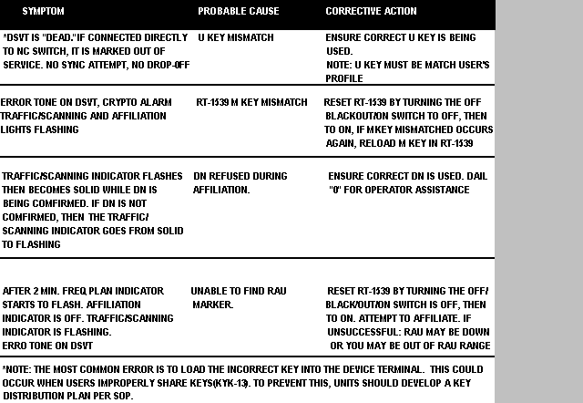
Table 3-6. MSRT troubleshooting chart.

Continue with Chapter 3
Table of Contents
Index
|
NEWSLETTER
|
| Join the GlobalSecurity.org mailing list |
|
|
|

