MSE TROUBLESHOOTING
LOS radio links connect MSE nodes. Each link is vital to the network while some links are more important than others. MSE network planners, coordinating with the corps and division G3 staffs, determine the priority for initializing and restoring links.
The LOS and NC switch equipment operators establish, operate, and maintain the links. This ensures the system is working properly. When a system fails or operations begin to degrade, the NMF operator notifies the SCC-2 of the situation. They also initiate troubleshooting procedures to find the cause of the problem. The troubleshooting process is a coordinated effort between MSE elements.
Every link in the MSE system has a label. The first half of the designator is the master link; the second half is the slave. The master terminal operator reports all link failure to the SCC-2. Failure reports are sent in message report format if possible. If not, the reports are sent to the SCC-2 by CNR, MSRT, DNVT, or courier. The SCC-2 must be informed of link failures as soon as possible. This allows the SCC-2 to react quickly to the failure.
Troubleshooting procedures are coordinated between the master and slave ends of the link using various means. The preferred means is by the secure DVOW. If the DVOW is not available, it may still be possible to use the engineering orderwire (EOW). Exercise caution when using the EOW, because it is not secure. CNR is another means to troubleshoot.
When a link outage occurs, it generates an error message at the NC or LEN switch. The switch operator must contact each assemblage within the failed link. Each assemblage operator provides assistance for loop back tests until the outage can be isolated and corrected. Particular caution must be taken when doing MDTG loop back tests (between an LOS(V)3 radio and the NC switch). MDTG loop back testing disrupts all communications on the tested MDTG.
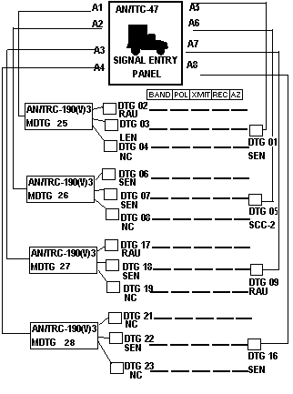
Maintain the trunk status of the links when troubleshooting using a status chart. See Figure 3-24.
Figure 3-24. NC switch trunk status diagram.

There are five loopbacks used inside the LOSs for link initialization. All five loops are available in each LOS type.
- 6-1-6 loop:
- Loopback from baseband units to associated LOS equipment.
- A good indication is L1 on the radio. - 6-2-6 loop:
- Loops data from the terminating assemblage back to the terminating assemblage (SEN/RAU/LEN).
- Good indications are L2 in the radio, and the TED in the terminating assemblage in resync and full operate condition.
- The operator must disconnect the antenna coaxial cable. - 6-3-6 loop:
- Disable signal from the baseband to the assemblage.
- A test pattern is generated on the transmit side of the baseband, which is looped back in the diplexer of the RF head. An error detector on the receive side of the baseband compares the receive pattern with the original.
- A good indication is L3 on the radio.
- The operator must disconnect the antenna coaxial cable. - Radio patch loopback:
- Loops data incoming from the distant end of a radio link back to the originating point.
- DVOW communications is nonfunctional using this loop. - 6-4-6 and 6-5-6 loops:
- 6-4-6 loop disables the signal from the baseband to the assemblage. A test pattern is generated in the baseband and transmitted to the distant end.
- 6-5-6 loop is used with the 6-4-6 loop. It loops incoming data from the 6-4-6 loopback to the originating LOS, where it is compared to the original signal.
- A good reading at the 6-4-6 end would be L4_ _E5 or L4_ _E6. If there were a fault, it would be indicated as follows: 4F4, as an example.
- A good reading at the 6-5-6 end would be L5_ _E5 or L6_ _E6. If there were a fault, it would be indicated as follows: 5F4, as an example.
- The readings are a measure of the bit error rate on the RF link.
- Each LOS in the link would perform a 6-4-6 loop to a 6-5-6, then reverse the loops.See TM 11-5800-216-10-4 for complete system and link troubleshooting and fault isolation procedures.
Continue with Chapter 3
Table of Contents
Index
NEWSLETTERJoin the GlobalSecurity.org mailing list

