

CHAPTER 4
Purification Operations
Section I
SITE AND SAFETY CONSIDERATIONS
PURIFICATION SITE
Select a water purification site from several proposed sites surveyed by the water reconnaissance teams. Once a site is chosen, position water purification units on level ground. Position the units so that no additional equipment is necessary to operate the raw water pumps, the distribution pumps, and the backwash pump. Use natural cover, when possible, for overhead concealment. Disconnect vehicles used to transport purification units from the purifiers during normal operations. The position of the storage tank area should be level but still have good drainage for runoff. Direct drainage away from the generator's operations. Use ground covers (tank bottoms) for all water tanks.
SAFETY PRECAUTIONS
Properly ground the purification unit. If the generator is separated from the purifier, ground it also. Fire extinguishers must be on site and a fire point established. All support legs to the purifier must be down and in the locked position. Operators will wear hearing protection when equipment is in operation. Block the wheels of the purification unit. Post no smoking signs near fuel points and operational areas. Do not store chemicals under direct sunlight. Use aprons, gloves, and goggles when handling chemicals.
Section II
600-GPH ROWPU
OPERATIONS
In order to properly operate the 600-GPH ROWPU, a soldier must understand the preparation, setup, initial start-up, PMCS, and shutdown. These procedures are listed below.
After selecting the best site, maneuver the unit into position. Remove the unit from the prime mover, and prepare it for self-support, grounding the generator and the purifier. Secure the safety step in place, and roll up the side canvas. Remove all stowed equipment.
Setup of Purifier
Connect the raw water and backwash systems. Connect the wastewater and vent vessel outlets. Connect all hoses to the chemical feed pump. Mix chemicals in their proper solutions, and calibrate the chemical feed pump. Connect the power cords from the raw water and backwash and distribution pumps to the purifier. Check the position on all drain and vent valves. Finally, check the position of switches on the control box.
Initial Start-Up
Follow the procedures outlined in TM 5-6115-465-12 to start the power generator. After ensuring the emergency stop button is pulled out, prime and start the raw water system. Once water is flowing into the purifier, start the chemical feed pump and set the polymer pump to run. Close the multimedia filter vent valve after a steady flow of water comes out. Next, start the booster pump. Close the cartridge filter vent valve after you observe a steady flow of water. Press the RO pump's reset button, then start the RO pump. Close the pulse dampener vent valve after you observe a steady flow of water. After 10 minutes, observe the RO vessel vent valve line for adequate flow and clarity of water. Next, examine the filtered water from cartridge filter drain valve one for clarity. Now set the sodium hex pump to run. Then slowly close the RO vessel vent valve. Slowly adjust the product water flow valve (being sure to carefully watch the brine flow gauge, the product water flow gauge, and the RO pressure gauge) to obtain the proper flow based on either a fresh or a saltwater source. Close the product water vent valve, and set the chlorine pump to run.
Operational Checks
Maintain proper flow rates into the purification unit at all times (27 to 33 GPM). Record the initial multimedia filter gauge reading. Maintain a psid reading of not more than 10 psid across the multimedia filter. A reading above 10 psid indicates the need to backwash the multimedia filter. Maintain the cartridge filter gauge reading from 1 to 20 psid while in operation. A reading higher than 20 psid indicates the need to replace the cartridge filters. The brine flow gauge reading will be from 16 to 24 GPM for normal operations. Product water flow readings for fresh and brackish water should not exceed 16 GPM while saltwater flows should read from 6 to 12 GPM. The RO pressure gauge reading should not exceed 500 psig for fresh water and 960 psig for saltwater. The RO vessel gauge should show a reading of 50 to 100 psid during normal operation. A reading higher than 100 psid indicates the need to clean the RO elements. Check the product water TDS (it must be below 1,000 ppm). Monitor the brine water flow into the backwash tank. Once the backwash tank is filled, the brine will be discharged back to the source. Monitor the low- and high-pressure lamps on the control box. If either light comes on, it may be necessary to press the emergency stop button. Continue operations, monitoring the chlorine residual in the product water to ensure 5 ppm is maintained. Stop operations for routine maintenance after 20 hours of operations, when the multimedia filter gauge rises above 10 psid, when the cartridge filter psid rises above 20, when the RO vessel gauge reads above 100 psid, for mechanical breakdown, or for normal shutdown.
To shut down the purifier for any of the above reasons, follow the procedures described here and in the order shown in Figure 4-1). First, set the chemical feed pumps to prime. Then open the regulate product flow valve and wait five minutes. Then open the product water and vessel vent valves. Open the cartridge filter vent valve, pulse dampener vent valve, and multimedia filter vent valve (all located on the control panel). Place all toggle switches on the control panel in the stop position (the RO pump, booster pump, chemical feed pump, and raw water pumps 1 and 2). Finally, follow the prescribed procedure for shutting down the generator.
| Editor's Note: This graphic is not viewable in HTML format. Check "Download Document" at the top of this file for an alternate format or obtain a printed copy of the document. |
Backwash
When shutting down the purifier to backwash the multimedia filter, follow these procedures. Place the RO element cleaning switch, located on the back of the control panel, to the off position. Press the reset button on the backwash timer. Check to ensure the backwash tank is full and the backwash strainer is clear. Open the backwash tank valve, and turn the backwash valve on the control panel to the backwash position. Then start the backwash pump with the switch located on the control panel. Backwash operations last approximately 13 minutes. Water flow rates vary during backwash from 0 to 70 GPM during low cycle to 0 to 120 GPM during high cycle. Check TM 5-4610-215-10 for the recommended settings on the backwash timer.
RO ELEMENT CLEANING
When the pressure differential across the RO membranes exceeds 100 psid, you need to clean the RO element. The first step is to backwash the multimedia filter. Then adjust the level of water in the backwash tank to 7 inches from the bottom. Disconnect the discharge hose from the discharge side of the backwash pump, and connect the vessel vent outlet hose to the discharge side of the backwash pump. Add 1 pound of citric acid to the backwash tank and stir. Make sure the product water flow, backwash tank, and vessel vent valves are open. Remove the product water hose from the product water tank, and place it downstream. Place the brine hose in the backwash tank. Switch on the RO element cleaning switch. The brine flow gauge should read 16 GPM or more. After five minutes of cleaning, check the pH of the brine. Add 1 pound of citric acid every five minutes until the pH is 3.5. After 3.5 pH is achieved, continue cleaning the RO elements for 45 minutes. During this entire process, the water temperature must not exceed 120°F. After the cleaning process is complete, turn off the RO element cleaning switch. Disconnect the vessel vent outlet hose from the discharge side of the backwash pump. Connect the backwash discharge hose back to the discharge side of the backwash pump. Drain the backwash tank into a sump. Do not place the product water hose into the product water tank until you have rinsed the RO systems for at least 10 minutes. For normal start-up, perform the procedures given in the paragraphs on Setup of Purifier and Initial Start-Up at the beginning of Section II. Operate the unit for 10 minutes with the regulate product flow valve at the fully open position to rinse the RO elements, the product water line, and the brine water line. Adjust the product water flow valve to obtain proper flow for the type of raw water source (fresh, brackish, or salt), and run the unit for three minutes with the product water line still discharging to waste. Finally, place the product water hose back into the product water tank.
Section III
3,000-GPH ROWPU
3,000-GPH ROWPU OPERATIONS
In order to start the 3,000-GPH ROWPU, the soldier must understand the preparation and initial set-up of the ROWPU. These procedures are listed below.
Preparation and Initial Set-Up of Purifier
After selecting the best site, maneuver the unit into the predetermined position. Drive-in access for the equipment must beat least 12 feet wide. The ground must be smooth and clear. You need a work area at least 35 feet by 70 feet for equipment maneuvering and set-up. Make a cleared path at least 3 feet wide to the water source. The work area must not be more than 30 feet above the raw water pump, and the raw water pump can be no more than 15 feet above the surface of the water source. The parking of the ROWPU (mounted on the trailer) can be no more than 200 feet from the raw water pump. The grade of the parking surface must not exceed 2 degrees crosswise and 5 degrees lengthwise. The storage tanks must also fit on this leveled surface (Figure 4-2).
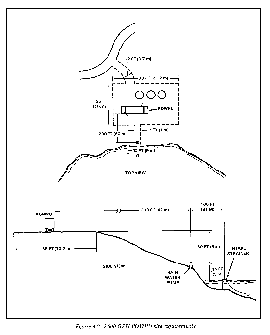
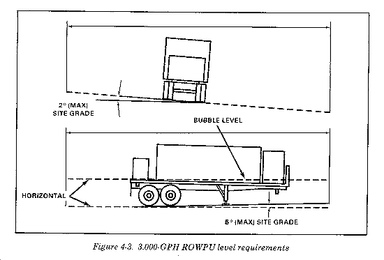
As you position the trailer, the raw water source must be to the right of the truck cab. Move the trailer into a position at the work site which will allow the front end to be slightly lower than the rear for water drainage. Position the trailer so that there is no more than a 2 percent side-to-side grade. Place wheel chocks under the wheels to prevent trailer movement. Place load boards under the landing gear. Lower the landing gear and unhook the trailer from the tractor. Using the bubble level mounted on the ROWPU, adjust the landing gear so that the front of the trailer is 1/2 bubble lower than the back of the trailer (Figure 4-3).
Unstrap and remove the two ROWPU access ladders, hand rails, and generator ladder from in front of the generator. Position the generator ladder and install one ROWPU access ladder at the door on the raw water side of the ROWPU. Ground the generator and the purifier. Remove all stowed equipment. Ensure the piping between the high-pressure pump skid and the ISO components do not have loose connections. Perform all before-operation PMCS. Follow the procedures in TM 5-4610-232-12 to establish electrical power.
As a preliminary to start-up, direct raw water through the media filter and out to waste through the forward flush valve. This helps to condition the filter bed and protects the RO elements from the high turbidity water always delivered in the first few minutes of filter start-up. The raw water pump can be no more than 30 feet from the water's edge. The water's depth must allow the intake strainer to be no less than 3 feet from the bottom of the water source. A water depth of 5 feet or more is preferred. Carry or use the shoulder straps to pull the raw water pump into place. Locate the pump within the limits shown in Figure 4-2 and upstream of the cyclone separator if the water source is a river or has a prevailing flow. Make note of tidal or river flood conditions and keep the pump located beyond the reach of the water. Keep the following suggestions in mind:
- Place the intake strainer in the center of narrow rivers in the deepest water.
- Place the intake strainer at least 50 feet from the shore in wider rivers.
- Place the intake strainer as far out as possible at ocean beaches.
- Place the raw water pump less than 30 feet from the water's edge.
- Flat tidal beaches may require moving the pump according to tide conditions.
- Prime the raw water pump. With the raw water pump primed, the raw water discharge hose should be hard with pressure when the booster pump is started. This should provide the 100 GPM feed flow required for flushing. If 100 GPM cannot be obtained, either the valves are incorrectly set or the raw water pump is unable to provide 100 GPM. If this is the case, check TM 5-4610-232-12 and automatic valves for proper settings. Look at the raw water discharge hose. If it is partially collapsed or pulsing, the problem is in the raw water system. Check the hose for kinks and sharp bends. All curves should be smoothly laid out. Check suction hose connections and the intake strainer.
Operation of the 3,000-GPH ROWPU
In addition to start-up, the soldier must understand how to shut down the ROWPU in either short-term or long-term status. These procedures are listed below.
Start up purifier. Start-up procedures vary with the status of the ROWPU at its last shutdown. Start-up procedures occur after the ROWPU is secured or drained, after an emergency stop, after the ROWPU is shut down to a stand-by condition, after a media filter backwash, and after RO element cleaning. Refer to TM 5-4610-232-12 for more specific guidance.
Shut down purifier to stand-by. There are procedures to follow when placing the ROWPU into stand-by status. These procedures are listed below.
The ROWPU is shut down to stand-by by fully opening the System Pressure Control Valve and pushing the High Pressure Pump Stop button.
After the feed flow drops below 60 GPM, push the Booster Pump Stop button.
Next push the Chemical Pump Stop and Raw Water Pump Stop buttons. The air compressor may be left on for short shutdowns. For shutdowns longer than one hour, the compressor should be turned off, the main circuit breaker turned off, and the generator shut down (diesel generators should not be run with small loads for long periods). If the ROWPU is kept in stand-by more than three hours, the RO elements may lose performance and require cleaning. Use the secured shutdown procedure when a longer shutdown is anticipated and the media filter has not been backwashed.
Start up after stand-by shutdown begins with media filter forward flush to waste. This flushes out the usual surge of dirty water when restarting the filter. A three-minute flush is required. This is important since you do not want to put dirt into the RO elements.
Shutdown to temporary secured status. Use this shutdown procedure when the ROWPU will be shut down for three hours to three days. You will need 525 gallons of potable water in this procedure. Be sure the water is available. Before shutdown, be sure that you have a 5-gallon can filled with product water. Use it in the poly-electrolyte tank during the start-up following shutdown. To temporarily secure the ROWPU, backwash the media filter and flush the system, following the procedures in TM 5-4610-232-12. A sanitizing flush will leave the RO vessels full of sodium bisulfite sanitizing solution. Drain this solution only if the ROWPU will be subject to freezing. To perform a sanitizing flush--
Shutdown to long-term secured status. Use this procedure when the ROWPU will be shut down for more than three days. You must have 1,000 gallons of potable water available. Before completing operations, fill a 5-gallon can with product water to use in the polyelectrolyte tank during the next start-up. The procedure for shutdown to long-term is the same as temporary-secured with the addition of removing the raw water suction hose at the pump and opening the drain valve on the pump. Disconnect the raw water discharge and waste hoses. Coil them and place them in a protected place. Turn off the air compressor, and open the air manifold bleed valves. Turn off the main circuit breaker and secure the generator. Drain the distribution systems. Pack the equipment for movement or storage. This completes shutdown of the ROWPU.
Alarm shutdowns. The alert horn will sound and the ROWPU will automatically shutdown for the reasons listed below. If this should happen, push the Alarm Silence button and refer to the troubleshooting chart in TM 5-4610-232-12 to locate and remedy the cause for shutdown.
If the feedwater pressure to the high-pressure pump is low, the Feed Pressure Low red light will go on.
If the high-pressure pump has excessive discharge pressure, the High Pressure Pump Pressure High red light will go on.
If the product water pressure is excessive, the Product Pressure High red light will go on.
If the clean/flush tank level is too low, the Clean/Flush low-level light will go on.
Emergency stop. Push the Emergency Stop button only when equipment failure or another problem demands immediate shutdown. Do not use the Emergency Stop button for routine shutdown. Pushing the Emergency Stop button immediately stops all motors within the ROWPU. To restart, pull out the Emergency Stop button, push the System Reset button, and push the Initiate button.
Operational Maintenance
To properly maintain the 3,000-GPH ROWPU, the soldier must understand backwash, RO element cleaning, systems flush, detergent clean, and citric acid clean. These procedures are listed below.
Backwash media filter. During a typical filter run (time between backwashes), the turbidity will initially decrease with time. After some time it will increase, indicating that the filter is so loaded with dirt that it can no longer remove dirt efficiently and requires backwashing. Record the media filter outlet turbidity at one-hour intervals. Note the time and polymer pump settings on the Media Filter Log. This log provides information essential to the best operation of the ROWPU. If the turbidity recorded is more than 0.5 NTU higher than the lowest recorded turbidity, the filter is no longer efficiently removing dirt and requires backwashing. If allowed by mission demands, backwash the media filter as soon as you find the polyelectrolyte optimum setting. After this first backwash, set the pump stroke back 5 percent from the determined optimum. Check the turbidity after the same length of filter run as when you first determined the optimum. If equal or less, keep this new setting. If higher, increase it 5 percent to the original optimum. Backwash media filter at least once each day, every six hours on rivers and lakes with high organics where turbidity is over 15 NTU and the temperature is over 70°F, whenever media filter outlet turbidity increases by more than 0.5 NTU over the lowest reading since the last backwash, whenever the Media Filter Plugged light and warning horn go on, or whenever the pressure drop reading is over 20 psid. Follow the procedures for backwashing the media filter outlined in TM 5-4610-232-12.
RO element cleaning. The RO elements may become fouled as described in Chapter 1. If the polymer has been carefully optimized and scale inhibitor, such as sodium hex, has been used, this fouling will be slow in most water sources. Rapid fouling may result in some water sources even when the polymer has been correctly optimized. Routine detergent cleaning at 100-hour intervals as noted by the high-pressure pump hourmeter will help reduce this fouling. Fouling may continue to build and can be noted by changes in operating conditions. You will then need an extended RO element cleaning.
Determine if extended RO element cleaning is needed. Use one or all of the following procedures to determine this.
Before cleaning the RO elements, make connections to form a closed loop. Add chemical solutions used in cleaning in the clean/flush tank. The chemical solutions are sent through the cleaning loop by the feedwater booster pump and the high-pressure pump. Open the cleaning bypass valve to bypass the media filter. The product utility hose returns product water to the clean/flush tank. The cleaning return valve and hose return the cleaning solution to the clean/flush tank.
Each of the assemblies must rest on a level, solid surface. The site must allow for easy drainage away from the assemblies. Large, heavy components, such as multimedia filters, should be staked out prior to actual emplacement. This assumes you have done the initial preparations (installation of cartridges and membranes, for example).
Before the 150,000-GPD RO WPU system can be operated, its individual components must be assembled and emplaced. These procedures are covered in more detail below.
Locate the raw water pump assembly near a water source and within 500 feet of the boost pump assembly. Connect as many hard-walled suction hose lengths as needed, but no more than 95 feet, to reach the water source. Couple the foot valve to one end of the hose and couple the other end to the raw water pump inlet. Couple as many collapsible hose sections as needed, but no more than 500 feet, to connect the raw water pump to the boost pump.
Boost Pump
Locate the boost pump assembly no more than 18 feet from the pretreatment assembly. Connect the collapsible hose from the discharge side of the boost pump to the pretreatment assembly inlet.
Pretreatment Assembly
Connect the pretreatment assembly to the multimedia filters using collapsible hoses. The pretreatment assembly must be within 12 feet of the multimedia filters. Install vent valves in the multimedia filters. Install coagulant aid and scale inhibitor drums and feeder pumps. Connect the pretreatment assembly outlet to the high-pressure pump inlet.
RO Block
Attach the high-pressure discharge hose from the high-pressure pump to the RO block. Attach collapsible hoses from the product water and brine water connections on the RO block. Insert the control box cable from the pretreatment skid into the socket on the high-pressure pump.
A number of checks must be made of the ROWPU system before it is put in operation. Prior to startup, complete the following actions:
A number of steps must be followed to startup the ROWPU system after the prestart checks have been completed. To start up the system, do the following:
NOTE: If the feedwater flow rate does not climb with this adjustment, check the raw water and boost pump pressure readings and adjust to normal operating limits.
The 150K ROWPU is designed to operate continuously in normal operation until manually shut down. In normal operation, you may manually start and stop the ROWPU equipment as often as needed to maintain the desired product water supply. Such short-term starts and stops involve only starting or stopping the pumps, checking the water flow rate, and adjusting the appropriate controls as needed. For longer than short-term, shut down the ROWPU as follows, in the order listed:
Before the 150,000-GPD ROWPU system is moved, you must prepare the system and its components. After performing the shutdown procedures described previously, prepare the system as follows:
To maintain the 150,000-GPD ROWPU in operating condition, you must periodically perform a number of maintenance services. These services are described in detail below.
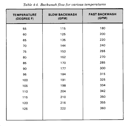
The backwash procedure uses filtered water from two of the filters to backwash the third one. During this procedure, turn off both chemical feed pumps and the high-pressure RO pump. Use the raw water and the booster pumps, as required, to establish the flow needed. The backwash procedure includes slow backwash, fast backwash, slow backwash again, and finally back to service. The backwash and rinse flow rates are adjusted by valve V-6. The exact amount of flow required depends on the water temperature: the cooler the water, the less flow is required; the warmer the water, the higher the flow required. For the backwash procedure, a feedwater temperature of 77°F is assumed as noted from the feedwater temperature indicator. At that temperature, the required flow rates are 160 GPM for slow backwash and 270 GPM for fast backwash. Refer to Table 4-4 for flow rates at other temperatures.
RO Membrane Cleaning
Perform the RO membrane cleaning procedure if the ROWPU's output deteriorates to an unacceptable, level because of reduced membrane efficiency. Perform these step-by-step cleaning procedures on an operating system which has been producing potable water and which can be found in TM 5-4610-229-10. Prior to starting this cleaning procedure, make sure you have the following equipment on hand: disconnect adapter, suction adapter assembly, hose coupling with 1- to 2-foot length of suction hose, and membrane cleaning compound (Hydrakleen-20).
Cartridge Filter Elements Replacement
Replace the cartridge filter elements when the differential pressure across the filter (the difference in pressure readings from PI-2 and PI-3) reaches 12 psig or more. The cartridge filter body contains 12 disposable filter elements. To replace filter elements, shut down operations and follow the procedures in TM 5-4610-229-10.
RO Membrane Element Replacement
Two operators are required for removing RO membrane elements. Be sure all pumps and feeders are off. Remove the RO membrane elements from the pressure tubes as detailed in TM 5-4610-229-10. Remember to push RO membrane elements from the pressure tube in the same direction as the feedwater flows. Push out the elements one at a time, using the unloading device. Support each RO membrane element until it is free of the pressure tube as it is being pushed out from the opposite end. Delay loading of the RO membrane elements until ready for system start-up. Otherwise, they may become wet prematurely, making their storage a consideration until ready to place the system into operation.
Multimedia Filter Media Replacement
The multimedia filters are loaded with new filter media at the factory. The old filter media is usually removed and discarded when proper flow and filtration can no longer be attained by means of backwashing. Avoid breathing dust from the filter media. Use an approved dust mask well-fitted to the face. Failure to comply can result in severe respiratory disorders and eventual death. Remove contaminated filter media by laying the filter unit on its side with the manway near the ground, fully open to access, and the bottom of the filter slightly elevated (about one foot off the ground). Remove the media from the tank by first reversing circulation to fluidize the media bed and allowing free flow of the fluidized media out at the manway. When no more media will flow from the tank, continue backflow while jetting the sand with a hose. Finally, it may be necessary to shut off backflow, enter the tank, and finish removing the last of the media by hand. Use care to avoid damage to coating on the inside of the filter body and manhole cover. When standing inside the filter body, be particularly careful to remove shoes/boots and to place feet carefully on the tank lining material. Do not step on or otherwise overstress any part of the underdrain assembly during erecting of the underdrain components or subsequent loading of the filter media. Refer to TM 5-4610-229-10 for more detailed guidance on filter media replacement.
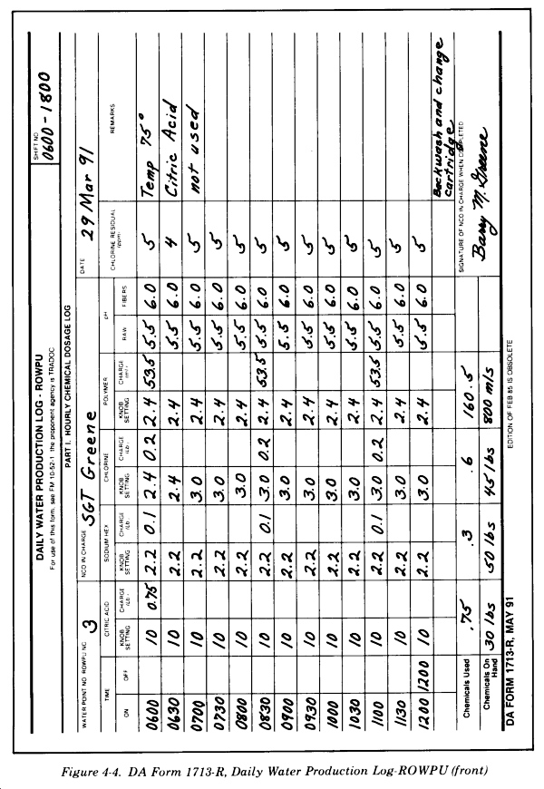
Daily water production logs are important because the information from these forms is used to schedule resupply of POL, chemicals, and maintenance. For this reason, the data entered on the production log should be complete and accurate. The daily water production log can tell you the quality of the raw water source by showing the amount of chemicals needed to make it potable. This will help in the future if you have to use the same or a similar source for a water point. See Figure 4-4 and Figure 4-5 for a sample completed form. Reproduce DA Form 1713-R locally on 8 1/2- by 1l-inch paper. A reproducible copy is in the back of this FM.
The following is guidance on completing the header portion of DA Form 1713-R.
The Water Point No/ROWPU No. Each water point will have a different number assigned to it as there will probably be two or more water points in different areas of the operation. Additionally, log each ROWPU by serial number. This will allow accurate measurement of each ROWPU's production time, consumption rates, and maintenance status. By using different numbers, you will be able to keep the information on each water point and each ROWPU separate.
NCO in Charge. By entering the name of the operator of the ROWPU, you know who is responsible for each ROWPU on each shift.
Shift No. By entering the shift number, you will have more information about shift operation of a specific ROWPU.
Date. At the start of each new day, enter the date. By checking the forms over a period of time, you can make an accurate estimate of the amount of chemicals and POL needed for extended operation.
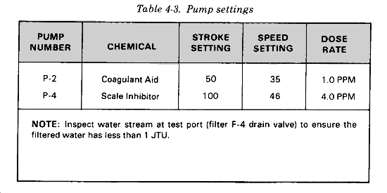
The following is guidance on completing the front of DA Form 1713-R. These columns will give you a report of the settings on the chemical pumps and the total amount of each chemical used during each operating shift, by water point number and ROWPU serial number.
Time. Enter the time the ROWPU was started and the time the equipment was shut down. This will give you the hours the ROWPU was in operation for the day. If available storage is filled and the ROWPU is put into standby, log operation stop and restart times. Also log the time the ROWPU is shut down for maintenance.
Citric Acid, Sodium Hex, Chlorine, and Polymer. Enter the initial knob setting and amount of chemical used for the initial charge. Make a separate log entry every time you recharge any of the chemical feed pumps. Also make a log entry if you change the knob settings. You should also make a log entry of the turbidity reading from the media filter every time you change the knob settings on the polymer pump.
pH. Enter the initial pH reading of the raw water and the pH from the product water. Also enter a periodic pH reading of raw and product water, noting the time of the reading in the Time column. Take these readings whenever a significant event occurs that would have an effect on the pH of treated water, and, in any event, at least every two hours. Also, log pH readings conducted during RO element cleaning.
Chlorine Residual. Enter the residual reading taken from the product water after at least 30 minutes contact time. Repeat at 30-minute intervals. Also note a temperature reading of the water. This would allow for correct chemical computation of chlorine based on temperature of the water.
Remarks. Enter the reason that the production of water was halted (for example, backwashing, RO cleaning, cartridge filter replacement). Also note any significant event that may affect water point operations.
Chemicals Used. Enter the total amount of each chemical used for the shift. Start a new form for each shift.
Chemicals on Hand. Enter the total amount of each chemical you have on hand for this ROWPU at the end of the shift. This amount should equal the Chemicals on Hand total from the previous shift minus the Chemicals Used totals. If they do not match, make a note in the Remarks column to explain the difference. If you receive supplies during your shift, note the amount of each chemical received in the Remarks column and add it to the Chemicals on Hand column. If supplies are issued to another ROWPU or another water unit, make a note in the Remarks column. Subtract the amount of each chemical issued from the Chemicals on Hand column.
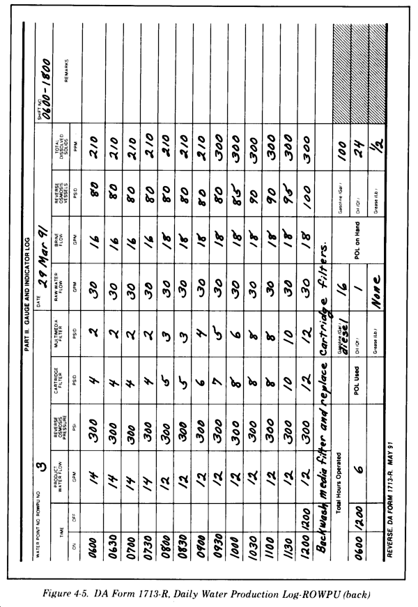
The following is guidance on completing the back of DA Form 1713-R. These columns will give you a report of the flow rates and operating pressures within the ROWPU during each operating shift by water point number and ROWPU serial number. These readings should be made hourly throughout the shift to monitor the operational condition of the ROWPU. The operator must take prescribed operational or maintenance steps based on these readings. Therefore, it is important that these readings be done frequently and accurately. This side of the form also allows you to compute the total gallons of product water purified on each shift. The bottom of the form is used as a daily inventory of POL. The amounts of POL and chemicals used during that shift are recorded as well as the balance left on hand at the end of the shift, By knowing the amount of POL and chemicals used per day and the amount you have on hand at the site, you will be able to order supplies before you run out.
Time. Enter the time you started the ROWPU and the time that the equipment was shut down. This will give the hours the ROWPU was in operation for the day. If available storage is filled and the ROWPU is put into stand-by, log the stop and restart times. Also log the time the ROWPU is shut down for maintenance.
Product Water Flow. Enter the reading from the product water flow gauge on the ROWPU. This reading should be the normal operating flow after initial start-up and should be measured continuously during operation.
Reverse Osmosis Pressure. Enter the reading from the RO pressure gauge. This reading should be the normal operating pressure for the source water (fresh, brackish, or salt). Take this reading and record it every hour during normal operations.
Cartridge Filter. Enter the pressure differential reading from the cartridge filter. This is the difference in pressure from the top to the bottom of the filter and indicates the status of the cartridges. When the pressure differential exceeds the established limit, replace the cartridges. When replacing cartridge filters, log the time you shut down and start up the ROWPU. Note the replacement in the Remarks column.
Media Filter. Enter the pressure differential reading from the media filter. This is the difference in pressure from the top to the bottom of the filter and indicates the status of the media. When the pressure differential exceeds the established limit, backwash the media filter. When backwashing the media filter, log the time you shut down and start up the ROWPU. Note that a backwash was conducted in the Remarks column.
Raw Water Flow. Enter the reading from the raw water flow gauge. You must maintain the proper flow of water into the ROWPU at all times. The ROWPU can sustain serious damage if sufficient flow is not maintained.
Brine Flow. Enter the reading from the brine flow gauge: Use this reading as an indicator of the status of your RO elements. If one or more of the elements fail, you would see a radical increase in the brine flow. Use this reading during RO element cleaning.
Reverse Osmosis Vessels. Enter the pressure differential reading from the RO vessels. This is the difference in pressure from the feedwater side to the product water side of the membrane. When the pressure differential exceeds the established limit, clean the RO elements. When cleaning the RO elements, log the time you shutdown and start up the ROWPU. Note the cleaning in the Remarks column. Also, note the flow rate readings that occur during the cleaning process.
Total Dissolved Solids. Enter the TDS reading. This reading can come from either the meters equipped on the ROWPU or from the individual TDS meter assigned to the operators. In either case, the TDS reading is made on the raw water (fresh, brackish, or salt) to determine production rates. TDS readings are also made on the product water from each bank of RO elements to determine if there has been membrane failure. Note in the Remarks column where the TDS reading is from.
To plan for resupply of POL in support of continuous water operations, you must know how much of each item is needed, where it will be needed, and when it will be needed. The how, where, and when are closely related. They all depend on the unit mission, the environment, how the mission is to be accomplished, and the unique characteristics of the unit. Plan ahead. Estimate fuel consumption as soon as possible so that adequate supplies can be requested and on hand when needed. The number of pieces of fuel-consuming equipment at each water point must be known to determine petroleum needs.
You are responsible for estimating your petroleum needs and submitting them in a timely manner. You must determine needs and report changes in your unit's initial consumption that warrant an adjustment in the supply distribution system. The most accurate method of estimating petroleum requirements is based on unit historical data which reflects the variables of weather, terrain, organizational strength, and operational vehicles and equipment. Use actual experience data when conditions are similar and data is reliable and has been verified.
Compute POL requirements on a scheduled basis, usually weekly or monthly. Consider the following factors when you calculate petroleum requirements.
Displacement. Consider the average distance and how often each vehicle moves. You need less fuel to move a unit over roads than to move a unit across country.
Supply. Certain vehicles must make round trip supply hauls during a displacement. Since the trips are made to supply points located at varying distances from the unit, determine an average round trip supply distance.
Service. Daily supplemental needs exist for moving vehicles in bivouac areas, for reconnaissance, for engine warm-up, and for long periods of low-gear operations. These are service requirements. Petroleum consumption depends on the nature of the operation, weather, roads, and terrain.
Housekeeping. Additional daily needs exist for gasoline-powered equipment and for operations, maintenance, and testing of power generators.
Waste. Waste covers evaporation, spills, and small combat losses. Compute it only when a unit is moving over roads in the combat zone. It is not included in the bulk estimate when the unit is moving over roads in the COMMZ or cross-country. Compute waste as 10 percent of the sum of all other consumption figures.
Stationary equipment. This factor applies to fuel-consuming equipment which does not provide its own power to move. Generators and gas-driven pumps are examples of such equipment. This type of equipment will operate 20 hours a day.
Review the completed daily production logs to determine the amount of chemicals used per day. This historical data will provide you with a good guideline to follow in estimating the amount of chemicals required. Review the logs over a period of time, not just one or two days. A key to your estimate will be the number of hours the equipment will be required to operate to support the mission. When estimating the amount of chemicals required to accomplish the mission, consider the following factors.
Section IV
150,000-GPD ROWPUSITE SELECTION
COMPONENT ASSEMBLY AND EMPLACEMENT
PRESTART CHECKS
START-UP PROCEDURES
SYSTEM SHUTDOWN
PREPARATION FOR MOVEMENT
MAINTENANCE
Section V
PRODUCTION REPORTSDAILY WATER PRODUCTION LOGS
Section VI
POL AND CHEMICAL REQUIREMENTSPOL REQUIREMENTS
CHEMICAL REQUIREMENTS