

APPENDIX E
Distribution Equipment Characteristics
Section I
FAWPSS
CHARACTERISTICS AND FEATURES
The FAWPSS is a portable, self-contained, gas- or diesel-operated unit that dispenses potable drinking water to troop units. The FAWPSS is operated by a 125-GPM centrifugal pump. Attach six 500-gallon water storage and dispensing drums, two at a time. Quick-disconnect couplings connect the drums to the pump. These drums provide water to the 125-GPM pump which, through hoses and valves, pumps water to four distribution nozzles where the water is discharged (Figure E-1).
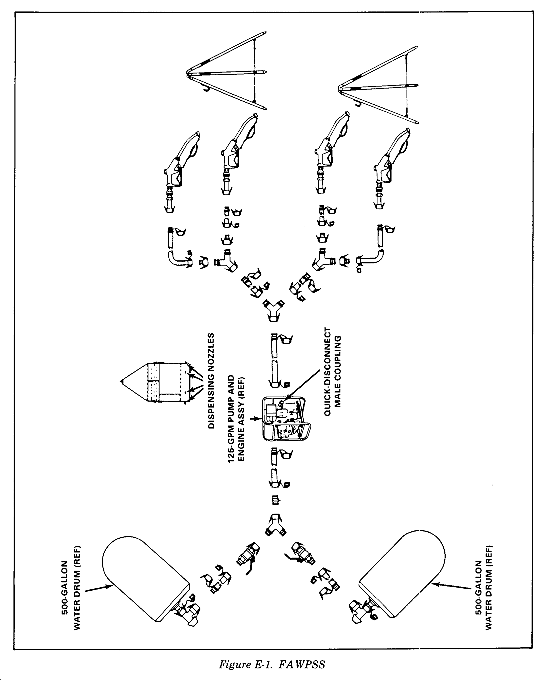
MAJOR COMPONENTS
The 125-GPM pump, 500-gallon water drum, hose, valve, nozzle, and stand assemblies are major components of the FAWPSS. They are described in the following paragraphs.
The 125-GPM pump and engine assembly provide power to operate the FAWPSS. The 125-GPM pump is a skid-mounted, self-priming centrifugal type water pump rated at 125 GPM at 50 feet head. It is powered by either a one-cylinder, air-cooled diesel engine rated at 3.8 HP at 3,600 RPM or a one-cylinder, air-cooled gas engine rated at 3 HP at 2,500 RPM. Its dimensions are 32 by 37 by 24 inches, and it weighs 144 pounds. Fuel is supplied by either an internal 1-gallon tank or a 5-gallon gas can with a flexible spout and fuel adapter assembly supplied with the set. Engine oil capacity is .79 quarts.
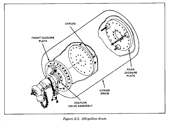
The 500-Gallon Water Drum
The six 500-gallon water drums are designed for a working pressure of 4 to 5 psi. When filled to its 500-gallon capacity, the drum is round in shape (Figure E-2). It can be towed, at speeds not to exceed 10 MPH, for short distances over smooth terrain using the towing and lifting yoke assembly. Two elbow coupler valve assemblies are provided with the 500-gallon water drums for ease of connection to the FAWPSS. Each drum is 7 by 4 feet; weighs 275 pounds empty, uncrated; and weighs 365 pounds crated. Crated size is 75 by 33 by 22 inches. The drum weighs over 4,500 pounds full.
- Towing and lifting yoke. Attach a towing and lifting yoke to the ends of the 500-gallon water drum for use in towing and lifting the drum.
- Tie-down kit. Use a tie-down kit to secure drums when they are being transported by cargo truck.
- Repair kits. The repair kits are furnished for emergency use only to prevent leakage until the operator can empty the drums. When these kits are used to make emergency repairs, do not move, tow, lift, or transport the drum until it is completely empty.
Hose, Valve, Nozzle, and Stand Assemblies
Two 2-inch valve assemblies provide for control of water during installation, operation, and disassembly of the FAWPSS. Various quick-disconnect, cam-locking hose assemblies are supplied with the FAWPSS. The quick-disconnect connectors provide for ease of assembly, disassembly, and maintenance. Each hose assembly is equipped with a protective cap on the male end and a protective plug on the female ale end to prevent contamination when not in use. Four nozzle assemblies are supplied with the system for dispensing water. Each nozzle assembly is equipped with a quick-disconnect connector and swivel for ease of operation. Two stand assemblies are supplied on which to place the nozzle assemblies when not in use.
Section II
SMFT
CHARACTERISTICS AND FEATURES
These tanks are designed and intended for transport of drinking water only. The assembled unit consists of a collapsible tank with pressure gauge, end fittings, tie-down straps, emergency repair items, hose, and tools to secure the tank safely on the trailer. The transport or contact with POL products will contaminate the tanks and result in permanent damage to the material and possible structural failure. These tanks can only be transported full or empty. A partially-filled tank will result in the lading shifting (surge) and will result in loss of vehicle control and possible rupture of the tank wall. When completely empty, roll up and store the tank. The tank is designed to be drained by gravity or suction pump only. Use of air pressure to unload the tank is not acceptable as it may cause the tank to burst under pressure.
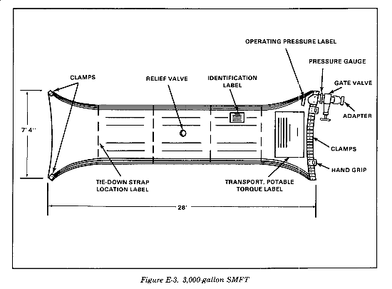
DS water supply units use the 3,000-gallon SMFTs (Figure E-3) to deliver water to major users that have no organic transportation capable of receiving needed water supplies directly from the water points. Additionally, transportation medium truck companies use these tanks during arid deployments for line haul of potable water from corps GS PWS/DSs to the division and brigade support area's PWS/DSs. These tanks are transported on M-871 22-ton semitrailers.
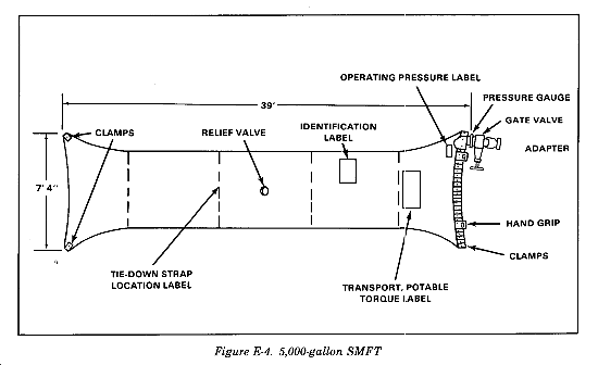
Medium truck companies use the 5,000-gallon SMFTs (Figure E-4) for line haul of potable water to and from TA and/or corps GS PWS/DSs, as well as some local haul to corps and EAC users that have no organic transportation capability. These tanks are transported on M-872 34-ton semitrailers.
MAJOR COMPONENTS
The 3,000-gallon and 5,000-gallon collapsible tanks are major components of the SMFT. They are described below.
Collapsible Tank, 3,000-Gallon
The tank is constructed of a chlorobutyl liner, a rubber-coated, multi-ply carcass, and an exterior weather, abrasion-resistant tread stock. When laid flat, the tank is 28 feet long, 7 feet 4 inches wide, and 4 inches high. When filled, it assumes a pillow-like shape approximately 27 feet long, 5 feet 2 inches wide, and 4 feet 6 inches high. Access to the tank interior is provided through the use of end clamps which you may remove. Handles are provided to facilitate positioning of the tank while empty.
- Fittings. The tank is furnished with a 4-inch filler/discharge assembly consisting of a male quick-disconnect, a 4-inch gate valve, a pressure gauge, two 10-foot lengths of 4-inch hose, and a manually operated relief valve located in the top center of the tank.
- Tie-down assembly. The tie-down assembly consists of four belts with eight ratchet take-up mechanisms and trailer attachments specifically designed to minimize tank movement during transport.
- Emergency repair kit. The emergency repair kit includes temporary repair items, such as plugs and clamps, to affect repair.
Collapsible Tank, 5,000-Gallon
The tank is constructed of a chlorobutyl liner, a rubber-coated, multi-ply carcass, and an exterior weather, abrasion-resistant tread stock. When laid flat, the tank is 39 feet long, 7 feet 4 inches wide, and 4 inches high. When filled, it assumes a pilow-like shape approximately 38 feet long, 5 feet 2 inches wide, and 4 feet 6 inches high. Access to the tank interior is provided through the use of end clamps which you may remove. Handles are provided to facilitate positioning of the tank while empty.
- Fittings. The tank is furnished with a 4-inch filler/discharge assembly consisting of a male gauge, two 10-foot lengths of 4-inch hose, and a manually operated relief valve located in the top center of the tank.
- Tie-down assembly. The tie-down assembly consists of four belts with eight ratchet take-up mechanisms and trailer attachments specifically designed to minimize tank movement during transport.
- Emergency repair kit. The emergency repair kit includes temporary repair items, such as plugs and clamps, to affect repair.
Section III
TWDS
CHARACTERISTICS AND FEATURES
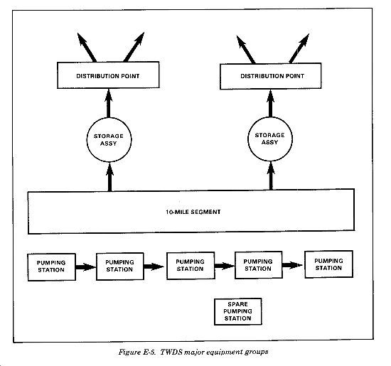
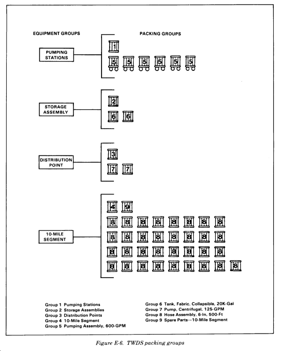
The TWDS is intended for operation by a water system consists of four major equipment groups: supply company or tactical water distribution two storage assemblies, two distribution points, teams in GS operations in arid environments. The system consists of four major equipment groups: two storage assemblies, two distribution points, one10-mile hose line segment, and six pumping stations (Figure E-5). The four equipment groups are further subdived into nine packing groups. This breakdown is shown in Figure E-6. The figure shows the packing groups for each equipment group, the number of crates in each packing group, and the name of each packing group. The nine packing groups that make up the TWDS contain a total of 47 or 48 crates, depending on whether there are 32 or 33 crates in group 8. the crates are plywood-sheathed, skidded, and equipped with headers for using a forklift. The crates are plainly marked to indicate the name of the equipment group and packing group to which the crate belongs. The system is capable of transporting water at 600GPM over level terrain.
MAJOR COMPONENTS
The pumping stations, storage assemblies, distribution points, and the 10-mile segment hose line are major components of the TWDS. They are described in the following paragraphs.
The TWDS comes with six trailer-mounted pumps, each capable of delivering 600 gallons of water per minute against a head or elevation gain of 350 feet. The pumps are the self-priming centrifugal type and are rated at 150 psi working pressure and -30 to 200 psi suction pressure. They are driven by six-cylinder, turbocharged diesel engines that have a four-hour (12-gallon) fuel capacity. The crankcase holds 6 quarts of oil and the radiator holds 7 gallons of antifreeze solution. The engine is rated at 120 HP at 2,400 RPM. The coupled pump and engine are mounted on a two-wheel trailer assembly that is equipped with highway lights, an inertial braking system, a manually operated parking brake, and jack stands. The trailer mounting enhances mobility and enables rapid deployment. A control panel mounted on the pump controls pump and engine operations.
Storage Assemblies
The TWDS comes with two 20K collapsible fabric tanks and accessory equipment. Depending on requirements, locate these storage assemblies together or at separate sites along the hose line. The assembly consists of the collapsible tank constructed of one-ply nylon fabric impregnated with chlorobutyl, vent and drain assemblies, a 1/2-inch drain hose, and control valve assembly. When filled, the tank assumes a pillow shape. Do not overfill the tank as it may burst. Do not use the tank on steeply sloping ground or it may roll. The maximum slope of the ground must not exceed 3 inches per 100 feet. Handles are provided along all sides of the tank for moving and positioning while empty. Pump water into the tank at 350 GPM until the tank is 90 percent filled; at that time, reduce the flow to 100 GPM. When not in use, fold or roll the tank and store it in the shipping container. Use the repair kit included with each tank to temporarily seal punctures or tears in the tank while it is full. Use a vulcanized rubber patch to permanently repair the tank when it is removed from service.
Distribution Points
The TWDS includes all necessary components to install two distribution points. These components include a 125-GPM pump, a hypochlorinator, and all necessary valves and hoses to connect two spigot-type elbow valves and two gravity nozzles. Two stand assemblies are provided to hold the elbow valves and nozzles when not in use. The distribution points are not designed for direct connection to the TWDS hose line. Use them in conjunction with a storage assembly to distribute water to SMFTs, water trailers, FAWPSS drums, and other water carriers.
The 126-GPM pump. The 125-GPM pump is a skid-mounted, self-priming centrifugal type water pump rated at 125 GPM at 50 feet head. It is powered by either a one-cylinder, air-cooled diesel engine rated at 3.8 HP at 3,600 RPM or a one-cylinder, air-cooled gas engine rated at 3 HP at 2,500 RPM. Its dimensions are 32 by 37 by 24 inches, and it weighs 144 pounds. Fuel is supplied by either an internal 1-gallon tank or a 5-gallon gas can with a flexible spout and fuel adapter assembly supplied with the set. Engine oil capacity is .79 quarts.
Hypochlorinator. The hypochlorinator unit provides automatic chlorination of the water before it is distributed. Automatic operation of the hypochlorination unit means that, during periods of changing flow, each gallon of water will receive the same amount of chlorine. This automatic operation is achieved by linking the operation of a water motor through a pilot valve to a hydraulically controlled hypochlorinator which regulates the amount of chlorine injected into the water passing through the unit. As the flow of water through the meter changes, the amount of chlorine injected into the water also changes. The hypochlorination unit incorporates a pressure regulating valve that maintains a pressure of at least 100 psi within the unit to ensure proper operation of the hypochlorinator. The hypochlorination unit can automatically treat from 2 to 100 gallons of water per minute. A range-adjusting valve is provided for establishing maximum accuracy of the unit within some portion of its operating range. At installation, the range-adjusting valve is positioned at its maximum setting of 100 GPM and then backed off, depending on chlorine demand and required chlorine residual. The hypochlorination unit is skid-mounted and portable. Three soldiers can place it into position. Quick-disconnect couplings are provided for installation in the threaded ports on the unit to enable hookup to the distribution point hose network. The unit is 33 by 30 by 31 inches and weighs 230 pounds.
Distribution hoses. The distribution point hoses are rigid-walled and equipped with quick-disconnect fittings to enable rapid installation. When connected, the hoses form a branching network that terminates at four manual valving stations. The valving stations can be equipped to conveniently distribute water to a variety of containers. With water flowing from all four stations, each station can distribute 15 to 20 gallons of water per minute.
10-Mile Segment Hose Line
The 10-mile segment includes all other components necessary to install, operate, maintain, and repack the TWDS. It contains the 500-foot hose line lengths used to connect pumping stations and storage assemblies, flaking boxes for hose line, pressure-reducing valve, and flaking box sling assembly. In addition, the 10-mile segment contains the road crossing guards and kits required to suspend, repair, and repack the hose line. A spare parts crate is also included with the 10-mile segment.
Hoses. The 6-inch by 500-foot hose line lengths are made from lightweight, collapsible rubber. Their being lightweight facilitates movement of the empty hose line by hand during laying or repacking operations. Because the hose line lengths are collapsible, compact them for movement or storage. The hose line lengths are made from a rubber that does not impart any unpleasant odor or taste to the water and remain flexible at temperatures of -25°F. Use victaulic couplings to connect the hose line lengths. These couplings compensate for expansion or contraction of the hose line and allow for slight misalignment of hose ends. At every other hose line connection, install a swivel joint to relieve any twisting in the hose line that may occur during installation or result from pressure surges afterward. An end cap is provided to terminate the hose line if dead-end service is required.
Flaking boxes. The flaking boxes consist of a welded structural steel frame with reinforced plastic panels. Each box measures 74 by 92 by 12 inches and is capable of holding one 500-foot hose line length. The flaking boxes are unpaneled on the top side to allow access to the box interior during repacking. The front of each box is sealed by a tailgate assembly which you remove and replace with a fabric breakaway prior to laying the hose line. The flaking boxes are equipped with four lifting clevises for attaching the lifting sling, channels for lifting with a forklift, and legs for nesting stacked flaking boxes. An eyebolt is provided as an anchor for the block and tackle used to compress the hose during repacking. The flaking boxes are intended to be handled in groups of four during the hose line laying operation. In this way, once the four hose line lengths are connected, 2,000 feet of hose line can be unfolded and laid from the back of one truck in about 10 minutes.
Pressure-reducing valve. Each TWDS includes one pressure-reducing valve. The valve is a portable, self-contained unit. It is mounted on a skid and equipped with victaulic fittings at the inlet and outlet ports for attachment to the hose line. The valve is installed in the hose line at a point where the water pressure is expected to exceed the normal operating pressure of 150 psi. It protects the hose line and other components from build-up of excessive pressure which can cause damage. In general, the pressure-reducing valve must be installed whenever there is a loss in elevation of 75 feet or more from one pumping station to the next. The pressure-reducing valve is an automatic valve designed to maintain a constant outlet pressure regardless of changes in the flow rate or inlet pressure. Basically, the valve consists of a main valve and a pilot control system. The control system is very sensitive to slight pressure changes and immediately controls the main valve to maintain the desired downstream pressure. Pressure-setting adjustment is made with a single adjusting screw. The adjusting screw is protected by a screw-type housing which can be sealed to discourage tampering. After installation, adjust the valve so that downstream hose line pressure does not exceed 150 psi and so the pressure at the suction port on the next downline pumping station is less than 120 psi. After initial adjustment, the valve requires no monitoring, except for periodic inspection. If downstream pressure changes, the valve automatically opens or closes to maintain the selected pressure.
Lifting sling. The TWDS lifting sling lifts flaking boxes in the field when a forklift is not available. The lifting sling is capable of handling a stack of up to four flaking boxes at one time. It is used with a crane with a minimum lifting capacity of 6,000 pounds.
Road crossing guards. The TWDS includes road crossing guards that protect the hose line from damage whenever it must be buried beneath a road or railroad right-of-way. The road crossing guards serve as a barrier between the buried hose and the heavy loads of vehicular traffic. Each road crossing guard is 5 feet in length. If the width of a road being crossed is 15 feet for example, you need three or four road crossing guards to protect the hose line. The TWDS comes with 24 road crossing guards.
Suspensions kit. The TWDS includes five metal chests containing kits of materials for constructing suspensions across streams, ponds, or gullies. Each kit contains enough rope, cable, saddles, sheaves blocks, shackles, turn buckles, and pickets to construct a suspension spanning 300 feet or two shorter spans with a total distance not to exceed 300 feet. Materials suitable for lashing tripods are not included in the kit and must be procured or fabricated locally.
Displacement and evacuation kit. The TWDS also comes with a displacement and evacuation kit. This kit is contained in a metal chest. It removes water and air from the hose line prior to repacking. A 250-cfm air compressor is provided to operate the kit. It forces a polyurethane ball that fits snugly within the hose through the hose, using compressed air as a propellant. As the ball is forced through the hose, it displaces all the water. When the ball arrives at the hose end, it is captured by a receiver. The hose end is then plugged and a vacuum is applied until the air within the hose is evacuated and the hose collapses. After the hose collapses, end caps are installed to prevent the hose from expanding before it is repacked.
Packing kit. The packing kit is contained in a metal chest and consists of items needed to repack the hose line in the flaking boxes. The kit includes a two-piece pullboard assembly and a chain hoist for compressing the hose in the flaking box. Two toggle clamps restrain the compressed hose while additional hose is flaked into the box and compressed. The toggle clamps are then moved forward and the process repeated until the hose line length is packed.
Repair kit. The TWDS comes with a repair kit for repair of the hose line. It is contained in a metal chest and includes enough adapters and victaulic couplings to make three repairs. Repairs consist of cutting out the damaged portion and splicing the ends together. The kit also includes two hose clamps for sealing the hose ends during repair.
Section IV
WATER TRAILERS AND MISCELLANEOUS EQUIPMENT
THE M149, M149A1, AND M625 2-WHEEL, 1 1/2-TON, 400-GALLON POTABLE WATER TANK TRAILERS
The M149, M149A1, and M625 tank trailers transport 400 gallons of water and are towed by a vehicle equipped with an Army standard pintle. An air supply and a 24-volt electrical system are required with the M149 and M149A1. The M625 requires a vehicle with a vacuum booster for its vacuum/hydraulic brake system and a 12-volt electrical system. The trailer may be towed at speeds up to 50 MPH. It has blackout lights and retractable landing gear support assemblies. Empty, the trailer weighs 2,900 pounds; loaded, it weighs 6,235 pounds. It is 161 inches long, 83 inches wide, and 78 inches high (Figure E-7). Major components are the water tank valve, faucets, and quick-disconnect coupling. They are described below.

The water tank valve releases water from the water tank into the piping to the faucets. The water tank valve is opened by pulling it out and closed by pushing it in.
The faucets are located under the faucet covers on both sides of the frame assembly forward of the water tank. Activate the faucets by pressing down on the levers, and turn them off by releasing the levers. The quick-disconnect coupling allows a field kitchen or a mobile water chiller to be connected to the water trailer. It is located under the faucet cover on the right side of the water trailer. It is opened by pulling out the two coupling rings and removing the dust plug. It is closed by inserting the dust plug and securing the coupling rings. The self-draining faucet is located at the rear of the stainless steel water tank on the M149A1 and M149A2 water trailers. It dispenses water from the water tank when the temperature is below freezing. Open the faucet by turning it counterclockwise to allow water to be released. Close it by turning it clockwise.
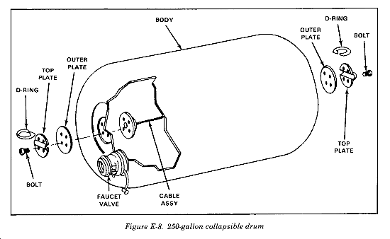
THE 250-GALLON, POTABLE WATER, NONVENTED, COLLAPSIBLE FABRIC WATER DRUM
The 250-gallon collapsible water drum (Figure E-8) is used for the storage and transportation of potable water. Many of the component parts (front and rear plates, for example) are identical to those used with the 500-gallon water drum. This drum is a durable, nonvented, collapsible rubber container designed for a working pressure of 4 to 5 psi and a maximum pressure of 30 psi. When filled to its 250-gallon capacity, the drum is cylindrical in shape and can also be towed with a towing and lifting yoke for short distances over smooth terrain at speeds not to exceed 10 MPH. The drum is constructed of water-resistant, synthetic rubber impregnated rayon. The interior front and rear plates are identical to those used in the 500-gallon water drum and are attached by wire rope cable assemblies to form a closure and an interior support for the drum. The front plate has a threaded coupler valve assembly identical to that used with the 500-gallon water drum. When empty, fold the drum so it can be transported by cargo trucks. Crated, the drum wide, and 18 inches high. Uncrated, the empty drum weighs 205 pounds; filled, it weighs 2,290 pounds. Major components are the towing and lifting yoke, tie-down kit, and repair kits. They are described below.
A towing and lifting yoke can be attached to the ends of the 250-gallon water drum for use in towing and lifting the drum.
A tie-down kit is used to secure drums when they are being transported by cargo truck.
The repair kits are furnished for emergency use only to prevent leakage until the operator can empty the drums. When using these kits to make emergency repairs, do not move, tow, lift, or transport the repaired drum until it is completely weighs 280 pounds, is 64 inches long, 32 inches empty.
THE 55-GALLON, POTABLE WATER, NONVENTED, COLLAPSIBLE FABRIC WATER DRUM
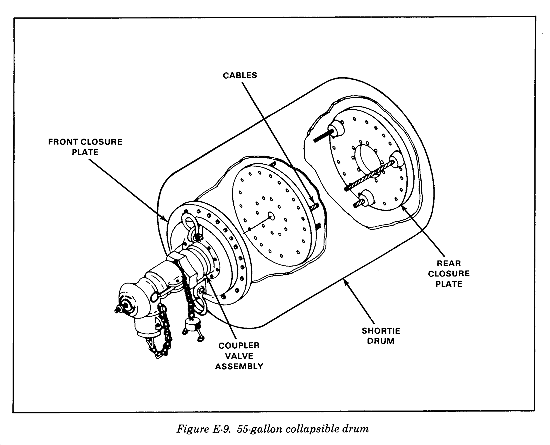
The 55-gallon collapsible water drum (Figure E-9) is used for the storage and transportation of potable water. This drum is a durable, nonvented, collapsible rubber container designed for a working pressure of 4 to 5 psi and a maximum pressure of 20 psi. When filled to its 55-gallon capacity, the drum is cylindrical in shape and is fitted with a faucet valve to permit the evacuation of its contents. The drum is constructed of water-resistant, synthetic rubber impregnated rayon. It is equipped with D-ring fitted end plates which are connected by a single wire rope cable. When empty, fold the drum to permit transportation by cargo trucks. Uncrated, the empty drum The tie-down kit and repair kits are major components of the drum. They are described below.
A tie-down kit is used to secure drums when they are being transported by cargo truck.
The repair kits are furnished for emergency use only to prevent leakage until the operator can empty the drums. When using these kits to make emergency repairs, do not move, tow, lift, or transport the repaired drum until it is completely empty.
|
NEWSLETTER
|
| Join the GlobalSecurity.org mailing list |
|
|
|