APPENDIX C
Purification Equipment Characteristics
Section I
600-GPH ROWPU
CHARACTERISTICS AND FEATURES
The 600-GPH ROWPU is used by divisional and brigade water purification elements and, in some cases, in corps and EAC units for the production of potable water from fresh, brackish, or saline water sources. The unit is trailer-mounted, air droppable, and requires a dedicated 5-ton prime mover. The 600-GPH ROWPU is designed to purify 960 gallons of water per hour from fresh water sources (1,000 ppm TDS or less) at a temperature of 77°F. This ROWPU can produce 760 gallons of water from saline water sources (35,000 ppm TDS or more) at a temperature of 77°F. As the raw water temperature drops, the production capability of the ROWPU is reduced, so that, at 50°F, this ROWPU produces 300 GPH on fresh water sources and 200 GPH on saline water sources. Additionally, other external factors, such as turbidity, also affect production rates. This ROWPU is capable of effectively removing potentially hazardous concentrations of all known chemical and biological agents and radioactive by-products of nuclear origin.
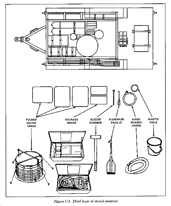
The ROWPU is 18 feet long, 8 feet high, and 8 feet wide. It weighs about 8 1/2 tons, including the trailer and the required 30KW generator. Figure C-1 shows the 600-GPH ROWPU from the top with the canvas cover removed. To provide room for all operating components, store material in layers. The top layer consists of rolled-up suction hoses on top of two folded water tanks. Stored between the tanks is a sledge hammer and a collapsed telescopic aluminum paddle. Next to the tanks is a stack of five plastic pails with chemical names on their sides. On the same side of the ROWPU, you will find two storage boxes fastened with a strap under the tanks. These boxes contain various chemicals, tools, and installation items. Nine sections of suction hose are stored on the side of the ROWPU frame.
In the second layer, you will find two raw water pumps and the backwash pump (Figure C-2). The pumps are covered with canvas and strapped down. The distribution pump is located at the rear of the unit, next to the generator. The ROWPU also includes a portable step which is strapped down with the distribution pump. On the right side are 1 1/2-inch and 2-inch diameter discharge canvas hoses, rolled up. A raw water float is in the center of the ROWPU next to the two NBC cylinders. Figure C-3 shows the ROWPU with all operating equipment removed.
MAJOR COMPONENTS
There are five major components of the 600-GPH ROWPU. They are described below.
There are three types of internal pumps. They are described below.
Booster pump. The booster pump forces water from the multimedia filter through the cartridge filter. The pump is a centrifugal type rated at 30 GPM at 50 feet of head. It is driven by an electric 1 HP motor. The control switch for the booster pump is located on the control panel between the RO Pump switch and the Chemical Feed Pump switch.
RO pump. The RO pump applies very high pressure (above 800 psi) to raw, filtered water from the cartridge filter to the RO pressure vessels. The pump is a five-piston, positive-displacement type rated at 51 GPM at 980 psi. A 20 HP electric motor drives it. The controls for the RO pump consist of a low-pressure lamp, a high-pressure lamp, a reset switch, and a start switch with indicator lamp. All RO controls and lamps are located on the control panel.
Chemical feed pumps. The chemical feed pumps inject treatment chemicals into the flow of water being treated. There are four chemical feed pumps, each rated at 3.17 GPH. The four pumps are driven by a 1/3 HP electric motor.
External Pumps
There are three different external pumps. They are described below.
Backwash pump. The backwash pump forces brine water from the brine tank through the multimedia filter to flush out accumulated material. It is also used to circulate the brine/citric acid solution through the RO elements during membrane cleaning. The pump is a centrifugal type rated at 120 GPM at 70 psi. A 10 HP electric motor drives it.
Distribution pump. This pump delivers water from the product storage tanks into the supported unit's vehicles and/or containers. The distribution pump is a centrifugal type rated at 30 GPM at 50 feet of head. A 1 HP electric motor drives it.
Raw water pumps. The two raw water pumps draw water from the source and move it to the ROWPU. Each raw water pump is a centrifugal type rated at 30 GPM at 105 feet of head. A 2 HP electric motor drives each pump.
Multimedia Filter
This filter is the first stage of treatment. The multimedia filter removes solids that pass through the input strainer. It is rated at 6.5 GPM per square foot.
Cartridge Filter
The cartridge filter removes suspended solids not removed from the process water by the multimedia filter. The cartridge canister contains eight cartridges. The cartridge canister is rated at 35 GPM maximum flow.
Pulse Dampener
The pulse dampener is a bell-shaped metal tank used to reduce pulses in the process water flow caused by the pistons in the positive displacement RO pump.
RO Vessels
The RO vessels (four each) are reinforced canisters designed to withstand the high pressures required for RO operations. Each vessel contains two RO membrane elements. Each element is a 6-inch roll of semipermeable, spiral-wound, poly-plastic membrane. Under pressure, the membrane allows the process of RO to separate the dissolved solids from the product water. The dissolved solids, called brine flow, are then passed from the ROWPU as waste.
Control Panel
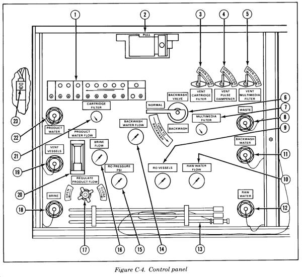
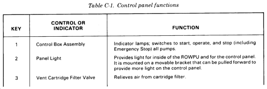
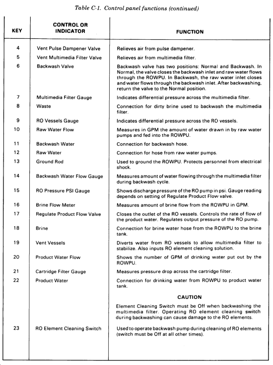
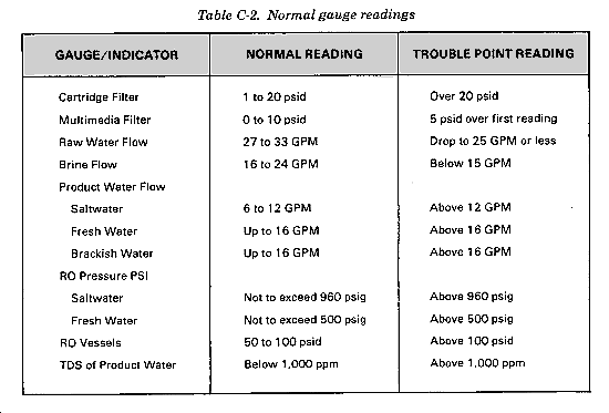
The control panel consists of various gauges, valves, lights, switches, and hose connections. The control box consists of the pump control switches and indicator lamps. The control box is located on the left side of the control panel. The circuit breaker panel is located in the junction box and consists of circuit breakers for the pumps, utility outlets, and backwash timer. The location of controls on the panel is shown in Figure C-4 and their functions are described in Table C-1. The normal reading of all gauges is shown in Table C-2.
Section II
3,000-GPH ROWPU
CHARACTERISTICS AND FEATURES
The 3,000-GPH ROWPU is intended for use by nondivisional corps and EAC units for DS and GS water production operations. It is contained within a special 8- by 8- by 20-foot ISO container with an overpack. The 3,000-GPH ROWPU is mounted on a standard 30-foot military trailer and can be shipped aboard USAF aircraft. It is powered by a 60KW utility diesel generator that is mounted on the rear of the trailer (Figure C-5). The 3,000-GPH ROWPU is designed to purify 3,000 gallons of water per hour from fresh water sources (1,000 ppm TDS or less) at a temperature of 77°F. This ROWPU can produce 2,000 gallons of water from saline water sources (35,000 ppm TDS or more) at a temperature of 77°F. As the raw water temperature drops, the production capability of the ROWPU is reduced, so that, at 50°F, this ROWPU produces 1,500 GPH on fresh water sources and 1,000 GPH on saline water sources. Other external factors, such as turbidity, also affect production rates. This ROWPU is capable of effectively removing potentially hazardous concentrations of all known chemical and biological agents and radioactive by-products of nuclear origin.
MAJOR COMPONENTS
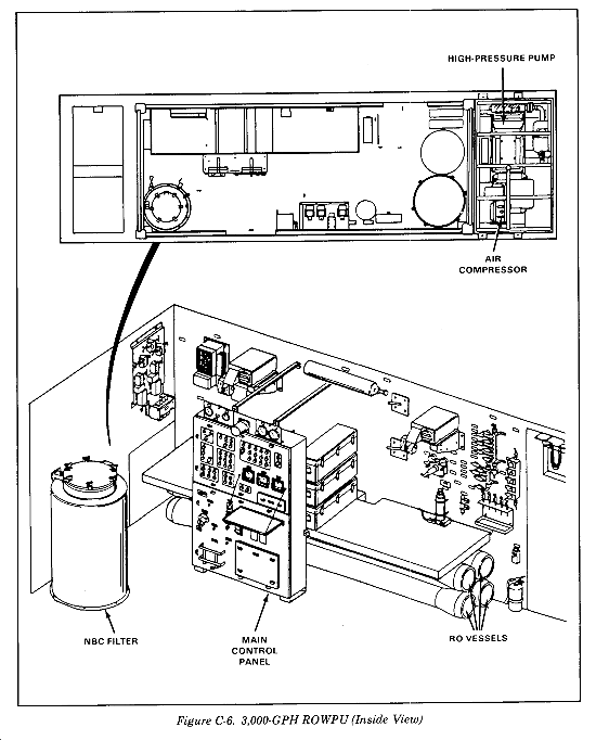
The raw water system, water filtration system, RO system, chemical feed system, and the air control system are major components of the 3,000-GPH ROWPU. See Figure C-6. They are described in the following paragraphs.
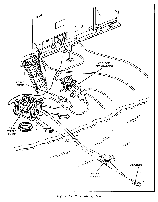
The raw water system draws raw water from the source thru a coarse screen. The raw water pump is a self-priming type pump. When the pump casing is filled with water and the pump is turned on, it will pull air out of the suction hose and pull the water up to the pump. Use a hand-operated prime pump to assist the raw water pump to quickly pull up the water. Use either a water can or the hand prime pump for initial priming. Without the hand pump, a lift of 15 feet through five hose sections will require six to eight minutes. With the hand pump, this is reduced to two to three minutes. Once the pump is primed, suction and discharge check valves (one-way flow valves) prevent the water from running back down to the water source when the pump is stopped. If these seal tightly, the pump will only require initial priming. Raw water pump discharge pressure delivers raw water to the cyclone separators where the water is swirled at a high rate of speed so that the heavier dirt and sand are thrown to the outside of the swirl and drip to the bottom where they are carried away through waste hoses. Any suspended solid which will settle in a glass in less than 20 minutes will be removed. Water which passes through the separators is delivered under pressure up to the ROWPU van where suction of a booster pump inside the van feeds pressurized water to the filtration components (Figure C-7).
Water Filtration System
In the water purification system, the raw water is filtered, treated with chemicals, and pressurized for the RO process. This system also includes air supply for automatic valve control.
The raw water is first treated by filtration. The filters reduce the turbidity of the raw water by removing suspended particles of fine clay, dirt, and organic matter. Turbidity not only makes water unfit to drink, but it may also foul the RO elements. Usually the water leaving the cartridge filter will have a turbidity of 0.5 to 1.5 NTU. This amount of turbidity usually causes slow fouling which can be removed by routine RO element cleaning. Fouling reduces the amount of water which can be produced by the ROWPU. The flow path is from the booster pump to the basket strainer, to the media filter, to the cartridge filter. This flow is described below.
The booster pump receives water from the raw water discharge hose. It pressurizes the water so it can go through the filtration steps.
The basket strainer removes remaining large particles such as leaves and wood pieces not removed by the cyclone separators. This prevents plugging of the water distributors inside the media filter. A spare strainer basket is carried on board to provide for a quick change when the basket strainer becomes blocked. When the basket strainer becomes blocked, the pressure at the basket strainer outlet becomes lower than the pressure at the basket strainer inlet. The ROWPU controls sense that pressure drop and set off a yellow warning light and pulsing horn.
The media filter removes most of the fine dirt, clay, and organic particles. The water enters the top of the filter and flows downward through one layer of coarse filter media and a final layer of very fine garnet sand. These layers are all supported by three layers of support gravel. A collector picks up the filtered water for discharge. The fine particles are too small to be removed by the straining action of the filter media. Many of the particles contain layers of electrical charges which prevent them from forming larger particles. The secret to removing these particles is the addition to the feedwater of a treatment chemical called polyelectrolyte. With the aid of this chemical, the filter can remove most of the dirt from the water, resulting in a turbidity between 0.5 and 2 NTU in most cases. Turbidity is measured by a continuous-reading turbidity meter. In time, the dirt trapped in the media filter will cause an increase in the pressure drop between the inlet and outlet pressure. A pressure gauge reads this difference and the ROWPU controls sense when this difference is too great. A warning light on the main control panel will come on and the warning horn will sound. The controls are then set by the operator to automatically backwash the media filter.
The cartridge filter contains 10 filter cartridges. Water goes through these filters for final (polishing) filtrations. When it has gone through this filter, the water will normally have a turbidity of 0.5 to 1.5 NTU. In time, these cartridges will become dirty. The pressure drop across the filter will increase. A pressure gauge reads this pressure drop, and the ROWPU controls sense when it is too high. A warning light will come on and the pulsing horn will sound. The ROWPU must be shut down and the dirty cartridges replaced.
RO System
After filtration to remove most of the suspended clay, dirt, and organic particles, the feedwater is further processed by RO. The feedwater is pressurized by a high-pressure pump and delivered to RO vessels containing RO elements. In the RO elements, the feedwater flows across sheets of membrane material. Some of the water passes through the membrane sheets and is collected to become product water. Most of the dissolved solids (salts) are blocked from passing through. Only one-third to one-half of the feedwater passes through the membrane sheets to become product water. The rest of the water containing most of the salt continues flowing past the membranes and exits the RO vessel as waste water. The amount of product water produced increases as the pressure increases.
The high-pressure pump is a three-plunger, positive displacement pump. It pumps 101 GPM pressurizing the water to the RO vessels. The pump is belt-driven by a 60 HP motor. Pump speed and delivery are fixed. The pump is mounted in a package separate from the IS0 container. Restriction of the water supply (blocked intake flow) will cause extreme vibration of the pump, and a low-pressure switch will automatically shut down the ROWPU.
The pressurized feedwater is discharged through a high-pressure hose to a manifold connecting the top two RO vessels. One-half of the flow enters each vessel; and as it passes across the membrane sheets, some of the water passes through and is collected in a central product water tube. The remaining feedwater, now containing a higher concentration of dissolved solids, discharges through an end fitting into a high-pressure pipe which directs the water back to the inlet end of the corresponding lower RO vessel. The water similarly passes across the membrane sheets within the lower vessels, producing additional product water.
The remaining feedwater leaving the bottom RO vessels is now waste water and contains concentrated salts. From each vessel it passes through an orifice to decrease the pressure. Then it is combined to pass through the high-pressure control valve and another orifice. This valve controls the working pressure of the system. By controlling the pressure of the system, the valve controls the amount of product water made. A high-pressure switch limits the pressure to 900 psig.
The product water flow at a fixed operating pressure is reduced as the source water TDS increases. The increased TDS causes an increase in natural opposing pressure called osmotic pressure. For this reason, the mission normal water production is the highest for fresh water, lower for brackish water, and lowest for sea water. The mission normal water production depends on water temperature. At a fixed operating pressure, the water production is also reduced as the source water temperature decreases.
The product water from each vessel is collected in a header and piped to the outlet. An in-line TDS meter monitors salt content to assure that product water meets potable water standards. A portable TDS meter is also used to measure the TDS from each vessel and the combined TDS from sample valves. Below 100 ppm TDS, use the portable meter. Just before the outlet, calcium hypochlorite is added. The chlorinated product water is capped potable water. When the TDS meets potable water standards, the product water hose is manually inserted into a storage tank. When the product water does not meet potable water standards, the hose is directed to waste. A pressure switch shuts down the ROWPU if hose blockage causes high pressure.
Chemical Feed System
There are three chemical injection pumps: one for polyelectrolyte, one for sequestrant, and one for hypochlorite. Each pump can be adjusted to control its delivery or turned off. Each of the three chemical solutions are contained in a tank. Each tank is labeled by name and a corresponding identifying symbol: polyelectrolyte - triangle; sequestrant - square; hypochlorite - circle. The tanks are manually filled with potable water from the utility hose. The polyelectrolyte and sequestrant are each supplied in a 1-gallon container with a graduated dispensing neck to allow for proper addition to the chemical tanks. Hypochlorite is added by emptying premeasured packages.
Polyelectrolyte is pumped from the polyelectrolyte tank by the polyelectrolyte pump. It is injected under pressure into the feedwater at the feedwater booster pump inlet. The polymer acts to trap very fine dirt particles in the media filter. These particles normally will not form larger particles because of electrical charges within their structures. The polymer is a long, string-like molecule which also has electrical charges along its length. As a polymer string contacts the fine particles, the electrical charges hold them and larger sticky floc particles are formed. When a floc particle contacts a grain of filter media, it has a good chance of sticking. Some polymer strings will stick to media grains and then trap fine dirt particles as they pass through the media filter. The amount of polymer used is very important. If there is not enough polymer, too many fine particles escape. If there is too much polymer, the electrical charges interfere with each other and many of the fine particles and some polymer escape from the filter. Use the correct amount of polymer to get the best removal of fine particles, as indicated by the lowest turbidity obtainable.
Inject sequestrant (scale inhibitor) into the feedwater to minimize or avoid the formation of scale in the RO elements. The amount, and whether it is needed at all, depends on the raw water source. Scale is formed when some of the dissolved solids become too concentrated to remain dissolved. The sequestrant interferes with scale formation. If scale forms, acid cleaning is required. Within the sequestrant, bacteria can grow and foul the RO elements. This is avoided by adding bisulfite when the sequestrant is mixed with the water.
Hypochlorite is injected by the backwash hypochlorite pump to the water flow during media filter backwash. It acts to kill algae and bacteria which can form a sticky matte on top of the filter media. If hypochlorite is not used, algae will make the media in the media filter so sticky that backwashing will not remove the dirt and algae and mud balling will occur. The tank and chemical packets are marked with a circle for easy identification. Hypochlorite is injected by the hypochlorite injection pump into the product water to provide chlorine residual amounts needed to keep the water safe to drink during distribution and use. The amount of chlorine is important and is set by the Army Surgeon General. Ten ppm is required in winter and 5 ppm in summer. Chlorine works slower in cold weather, so more is needed.
Air Control System
The air compressor, mounted in the high-pressure pump package, is the source of air pressure to operate automatic valves and aid in media filter backwash. Compressed air is stored in the air reservoir which provides 1,800 psig service air. An air regulator valve reduces the air pressure to 85 psig for service use. An air dryer further reduces moisture from the low-pressure air used for valves and instruments. Air manifolds distribute the service air.
THE MEDIA FILTER BACKWASH
Backwash the media filter whenever the Media Filter Plugged warning light and horn come on or at least once a day if the horn and light do not come on. Routinely backwash the media filter every six hours when it is operating on a river or lake with a heavy concentration of organic material and a temperature over 70°F. This action avoids a thick layer of sticky organic material building on the surface of the filter bed. This material is the principle cause of mud ball formation. The filter media and the sticky organic material form large sticky balls during backwash. These balls sink and lead to extremely poor filter performance. On some waters, most of the places in the filter bed for the dirt to stick are used up without causing a high enough pressure drop to set off the alarm. When this happens, the filtered water turbidity begins to increase. If it increases by more than 0.5 NTU, backwash the filter.
RO MEMBRANE FOULING
Suspended solids in the feedwater are driven to the membrane surface and have a tendency to stick. As this happens, the water flow through the membrane is restricted. The product flow decreases or the operating pressure must be increased to obtain a constant flow. This problem is called fouling. The lower the turbidity obtained from the filters, the lower the rate of fouling will be. Fouling cannot be avoided, but it can be decreased by good operations. Regular cleaning of the RO elements is part of the operational procedures for the ROWPU.
NBC OPERATIONS
The ROWPU can decontaminate raw water which contains NBC agents. The feedwater filters and the RO elements remove most of these agents. However, safe levels are not assured. When decontaminating raw water during NBC missions, the product water is additionally passed through the NBC filter for final agent removal. After filtration, the water is chlorinated. The NBC filter is connected by jumper hoses when it is required. The top half of the filter contains a layer of activated carbon. The lower half contains a layer of ion exchange resin beads. The NBC agents are absorbed by these materials. The carbon and resin beads are replaced after each 100 hours of water production to assure there is always a capability to absorb NBC materials.
Section III
150,000-GPD ROWPU
CHARACTERISTICS AND FEATURES
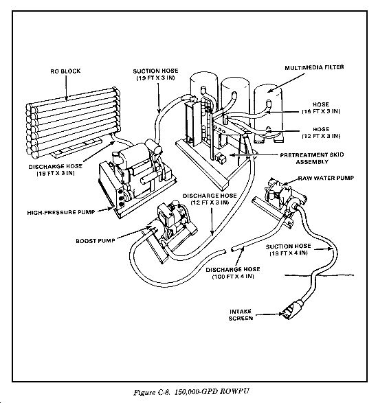
The 150,000-GPD ROWPU is intended for use by corps and EAC water purification units to support operations requiring GS water supply operations. The unit will be provided to operating units as required. Production capability is based upon a 20-hour-per-day operation. The unit is mobile when disassembled. Required assembly time will be less than three days. The unit is designed to operate on seawater, and is not specially designed to reduce the presence of chemical and biological agents and radioactive by-products; however, 90 to 95 percent reduction in NBC agent concentration is inherent in its operation. The process, however, does not ensure potable water in an active NBC environment. The ROWPU (Figure C-8) consists of a series of diesel engine-driven pumps, filters, and a RO block assembly capable of converting 150,000 GPD of brackish water or seawater to drinking water.
MAJOR COMPONENTS
The raw water pump assembly, boost pump assembly, pretreatment assembly, multimedia filters, high-pressure pump assembly, and the RO block assembly are major components of the 150,000-GPH ROWPU. These components are described below.
The raw water pump assembly consists of a skid-mounted diesel engine/centrifugal pump combination. The one-cylinder diesel engine is rated at 6.7 HP at 2,000 RPM. Start the engine by a hand crank or with an electric starter. The centrifugal, direct-coupled pump is rated at 350 GPM at 30 psi. The pump takes water from a remote location up to 95 feet away and pumps it to the boost pump assembly up to 500 feet away. The dimensions of the assembly are 49 by 33 by 29 inches, its weight is 687 pounds, its oil capacity is 2.3 quarts, and its fuel tank capacity is 2 gallons.
NOTE: In recent deployments, this pump has been replaced by the three-cylinder 350-GPM pump described in Appendix D of this manual.
Boost Pump Assembly
The boost pump assembly consists of a skid-mounted diesel engine/centrifugal pump combination. The three-cylinder diesel engine is rated at 48 HP at 3,000 RPM. An electric starter starts the engine and drives the pump through a belt. The centrifugal pump is rated at 350 GPM at 115 psi. This pump provides the pressure to maintain feedwater flow to the pretreatment assembly, through the multimedia filters, back through the pretreatment assembly, and to the high-pressure pump assembly. The dimensions of the assembly are 69 by 40 by 37 inches, its weight is 1,500 pounds, its oil capacity is 8.1 quarts, and its fuel tank capacity is 15 gallons.
Pretreatment Assembly
The pretreatment assembly consists of a skid-mounted gauge panel, two chemical metering pumps, interconnecting piping, valves, and cartridge filters. A manually adjustable chemical metering pump doses the feedwater with a coagulant aid as it enters the pretreatment assembly. The chemical metering pumps are electric-driven, piston diaphragm types rated at. 7 GPH at 145 psi. The feedwater then goes to the multimedia filter where, with the aid of the coagulant, most particles are removed. It returns to the pretreatment assembly where it is dosed with a scale inhibitor by the second manually adjustable chemical metering pump. The scale inhibitor reduces the formation of scale and fouling of the RO membranes. The feedwater continues on to the cartridge filter where the remaining fine particles are removed. The dimensions of the assembly are 111 by 38 by 71 inches, and it weighs 1,518 pounds.
Multimedia Filters
The multimedia filters consist of three identical skid-mounted filters with lifting eyes. The pretreatment assembly receives water at the top of the filter where it flows downward through the media and returns from the bottom of the filter to the pretreatment assembly. Each multimedia filter is 56 by 48 by 82 inches and weighs 5,052 pounds dry and 9,217 pounds wet.
High-Pressure Pump Assembly
The high-pressure pump assembly consists of a skid-mounted diesel engine/jet pump combination. The high-pressure pump diesel engine is a six-cylinder diesel rated at 325 HP at 1,800 RPM. The pump, a roto-jet driven by the diesel engine through a series of matched V-belts, is rated at 350 GPM at 805 psi. The high-pressure pump assembly raises the feed water from the pretreatment assembly to the pressures needed to operate the RO block. The dimension of the assembly is 101 by 75 by 82 inches, its weight is 5,760 pounds, its fuel tank capacity is 25 gallons, its oil capacity is 9 gallons, and its coolant capacity is 9 gallons.
RO Block Assembly
The RO block assembly consists of 16 skid-mounted RO tube assemblies, each of which olds five RO membrane elements. Water coming from the high-pressure pump enters the tubes where the membrane elements separate it into drinking water and brine concentrate. The dimension of the assembly is 53 by 229 by 92 inches, and it weighs 4,000 pounds dry.
|
NEWSLETTER
|
| Join the GlobalSecurity.org mailing list |
|
|
|


