|
CHAPTER 3 WATER SUPPLY COMPANY
|
Section I
OVERVIEW
This section is for the company commander.
MISSION
The mission of the water supply company is to store and distribute potable water to divisional and nondivisional units in a combined DS and GS role. To do this, your company establishes and operates at least one temporary water storage and distribution system. It also lays, operates, and retrieves the TWDS and maintains part of the command water reserve stocks.
CAPABILITIES
Your company's capabilities are determined by personnel strength levels prescribed by (TOE 10468L. Company personnel also have defense and maintenance responsibilities.
Full Strength
At full strength (TOE Level 1) and operating on two 12-hour shifts, your company can--
- Install and operate two 10-mile TWDSs. The TWDSs can transfer 600,000 gallons of water per day when they are operated in tandem. Operated separately, the two TWDSs can transfer 1,200,000 gallons of water per day. Each section of the TWDS can issue 200,000 gallons of water per day.
- Operate 32 collapsible, bulk water storage tanks. Each tank can hold 50,000 gallons of water, so the capacity of your company tanks is 1,600,000 gallons.
- Store part of the command water reserve stock (up to 1,600,000 gallons).
- Operate up to eight DS issue points.
Reduced Strength
TOE Strength Level 2 reduces the operational capability to about 90 percent, and Strength Level 3 reduces it to about 80 percent. For more on strength levels, see AR 220-1.
Attached Strength
When the TWDS teams (TOE 10570LB) are attached to your company, you can operate a water storage and distribution system for up to 80 miles. More on TWDS teams can be found later in this chapter.
Defense
Members of your company can help in the coordinated defense of the company area or installation. More on unit defense is in Chapter 1.
Maintenance
Your company performs unit maintenance on its equipment, except CE equipment. More on unit maintenance is presented later in this chapter.
REQUIRED SUPPORT
Your company depends on appropriate elements of the theater army for legal, medical, financial, personnel, and administrative support. It depends on the headquarters and headquarters company and the water supply battalion for CE unit maintenance and for religious support. It also depends on--
- Additional security forces when physical security or defense needs exceed capability.
- Water purification teams or a water purification detachment for potable water (see Chapter 4).
- Preventive medicine personnel to determine whether the water supplied by your company is potable.
MOBILITY
The mobility of your company is limited by the number of vehicles you have and the number of personnel and amount of equipment and supplies you must move. Your company has 29,720 pounds (1,940 cubic feet) of TOE equipment. Your company can move 255,000 pounds (9,412 cubic feet) of equipment and supplies in one lift using company assets.
ORGANIZATION
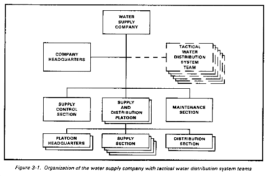
Your company is organized to meet mission requirements in an arid environment. As the demand for water increases with the growth of the theater, your company may also expand. Figure 3-1 shows the number of elements in your company at maximum size. Note that as many as six tactical water distribution system teams may be attached to your company. Your company is employed in the corps or COMMZ area. Normally, the company will be attached to a water supply battalion.
Section II
COMPANY HEADQUARTERS
This section is for the company commander.
MISSION
Using your company headquarters staff, you command and control the company. Your headquarters is responsible for internal operations of the company. This includes billeting, training, discipline, communications, administration, and security. Your supply sergeant provides unit supplies. Food service personnel provide food service support.
PERSONNEL
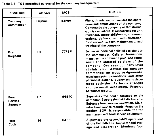
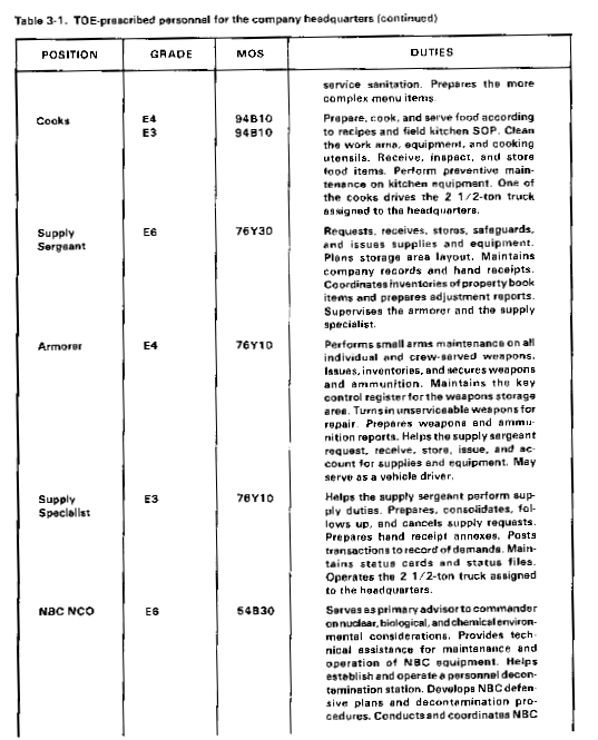
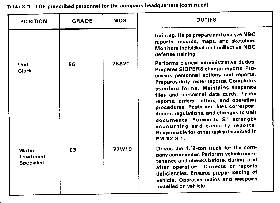
Your most valuable resources are your soldiers. To use them effectively, you must know their duties. Table 3-1 lists TOE-prescribed personnel by position, grade, MOS, and duties. Duties of other company personnel are described later in this chapter.
Section III
SUPPLY CONTROL SECTION
This section is for the water supply officer.
MISSION
The mission of the supply control section is to control company water supply activities. Your section ensures that the company follows directives received from the water supply battalion about the receipt, storage, and issue of water. Your personnel prepare plans and schedules for water that comes in and water that is sent out. Your personnel prepare and forward required reports to the battalion headquarters and to the company operating sections. They coordinate transportation for the delivery of water to the water points. They also establish and maintain water activity records.
PERSONNEL
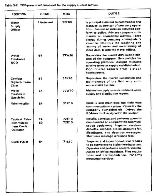
Your most valuable resources are your soldiers. To use them effectively, you must know their duties. Table 3-2 lists TOE-prescribed personnel of your section by position, grade, MOS, and duties.
LAYOUT
Before your personnel set up operations, you should develop a layout plan and show it to them. On your plan, show the position of section equipment in a medium GP tent. Plan for an administrative and records control area, a communications area, and a water testing area. Include a copy of the layout in the supply control section of the company SOP. Alter the layout to include the use of any space available in permanent buildings.
OPERATIONS
The supply control section is the mission control element of the company. It supervises and directs the company water supply activities. It provides the necessary personnel to operate as the control element of unit mission activities.
Control
Your soldiers coordinate water support activities with the battalion headquarters and the operating platoons. They inform the battalion headquarters of company transportation needs. The battalion headquarters manages your water support assets. You receive water directives and documents from the battalion headquarters and submit reports to it.
Communication
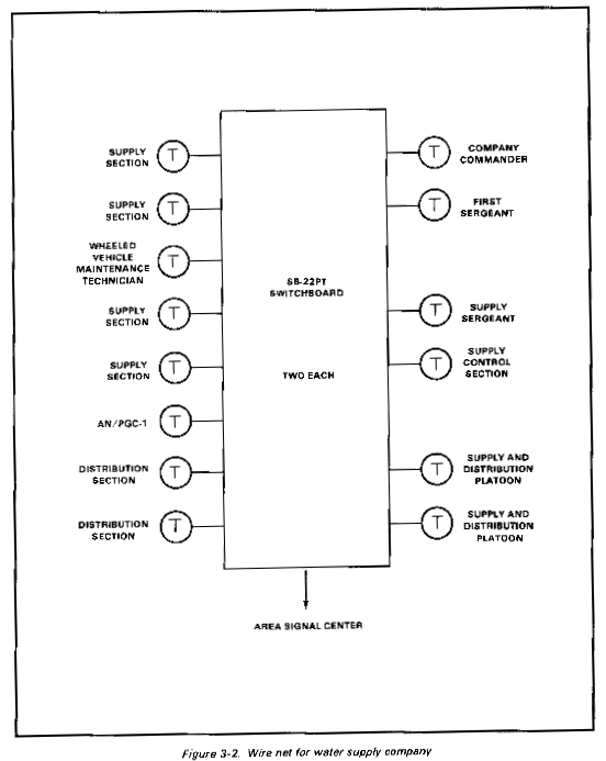
Your section must establish and maintain wire net communications for the company. Your section is authorized communications equipment and telecommunications center operators and tactical wire operations specialists to operate and maintain the equipment.
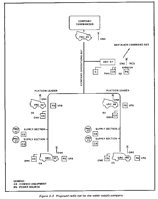
Setup. Advance party personnel, including the tactical wire operations specialist, will have already laid and installed wire for telephones, switchboards, and teletypes according to the wire net diagram. Wire is the primary means of communications provided the company. The organic net provides telephones and switchboards for internal communications with higher, subordinate, and adjacent units. Teletypewriters and associated equipment allow quick and urgent transmission of communications. The teletypewriter also allows receipt of water requirements and the transmission of reports and advice to and from higher headquarters. Wire and radio net diagrams are shown in Figures 3-2 and 3-3.
Operation and maintenance. The water operations sergeant or an assistant should develop manning schedules to ensure adequate operation of communications equipment. Make sure that correct procedures are used and that all personnel follow COMSEC measures to prevent jamming, interference, and deception. Have supervisors make sure that equipment maintenance manuals are complete and up to date for all communications items.
Records
The water supply control specialist maintains water activity records in your section. Your section has records of all water stored in the operating sections of the company. They are filed in water point location sequence. Records show by location the total water storage capabilities, the total water on hand, the total water received, and the total water issued.
Daily reports. Have each of the water sections submit a daily report. Outline the procedures in your section SOP. Appendix A shows a suggested format for a daily report. Use these reports from the water sections to manage your water assets and to report the amount of water to higher headquarters.
DA Form 1717-R. You report the amount of water distributed to all units on a daily basis. Use DA Form 1717-R (Water Point Daily Distribution Summary) to do this. Appendix A has a sample of DA Form 1717-R. This form is also in FM 10-52, Appendix A.
Inventories
Make sure you inventory your water supplies periodically. Have your water treatment NCO coordinate all inventories. However, you are responsible for scheduling inventories and providing SOP directives for them for the operating sections.
Schedules. Schedule staggered cyclic inventories so that all supply sections will not be taking inventory at the same time. You must establish inventory dates and cutoff dates.
SOP. Prepare an SOP to be used in inventorying water. AR 710-2 and FM 38-741 have information for use in preparing the inventory SOP. They include preinventory procedures, duties of inventory personnel, preparation and processing of inventory adjustment documents, and actions after inventory. Once the SOP is set, issue a directive naming inventory team members. As a minimum, the SOP should cover the following:
- Receiving section cutoff time and date.
- Assignment and responsibilities of inventory count team personnel.
- Areas not inventoried.
- Assignment of inventory voucher numbers.
- Inventory records.
- Issue during inventory.
- Correction of water activity records.
- After-inventory actions.
Procedures. The water treatment specialist is responsible for preparing inventory records and reports. When an inventory is completed, he will total the quantities held in different locations, compare inventories with the recorded balances on water activity forms, and submit the inventory total through the battalion to the supporting MMC or petroleum group.
Forecasts
Every 24 hours of operation, the water treatment specialists assigned to each of the two platoon headquarters will consolidate and forward to the supply control section the status reports received from each of its two supply sections. In turn, the water treatment specialist assigned to the supply control section will consolidate and forward to battalion headquarters the status reports received from each of the two platoon headquarters every 24 hours of operation. Water battalions will then submit status reports to their supporting MMC or petroleum group, which will in turn submit reports to the theater army MMC. Submission of status reports will depend on the theater situation and will be stated in directives, SOPs, or water distribution plans. Daily reports provide the company water supply officer a source from which to estimate receipts and issues for the next 24 hours of operation. They are of particular value when a company assumes the support of like units performing like missions. It is also from these estimates that the water supply officer forecasts estimates for transportation requirements. The daily status report is an informal report with no set format.
Transportation
The water supply company is authorized vehicles for internal movement only. In order to receive and issue water by truck, you must rely on semitrailer-mounted fabric tanks from the transportation medium truck company. Since both companies are attached to the water supply battalion, coordination will be through battalion headquarters. Exact procedures for requesting the semitrailers should be stated in both battalion and company SOPs. The water treatment supervisors plan work flow and sequence. They have the required personnel and equipment on hand for prompt loading and off-loading. Therefore, the water supply officer or his NCOs will need to inform platoon headquarters (and through the platoon headquarters a water treatment supervisor in the supply section or his assistant) of the--
- Quantity of water to be received or issued.
- Means of transport.
- Approximate time of arrival at the loading or off-loading site.
Quality Control
Quality control requires more than periodic testing. It also requires proper handling procedures during storage and during loading and unloading operations. Quality control is not only determining the quality of water but maintaining it so that the water is suitable for its intended use. The water treatment specialists in the supply and distribution platoon headquarters are responsible for quality control. However, you should continually check to make sure they are doing their jobs. Details on water quality are in FM 10-52, Chapter 1.
Section IV
SUPPLY AND DISTRIBUTION PLATOON HEADQUARTERS
This section is for the supply and distribution platoon leader.
MISSION
The company has two supply and distribution platoons. The mission of each supply and distribution platoon headquarters is to supervise and control platoon activities, reconnoiter and select operating sites, and perform quality surveillance.
PERSONNEL
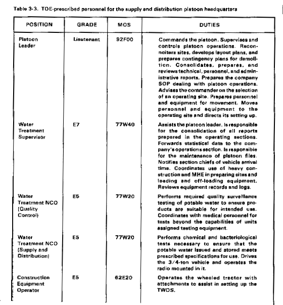
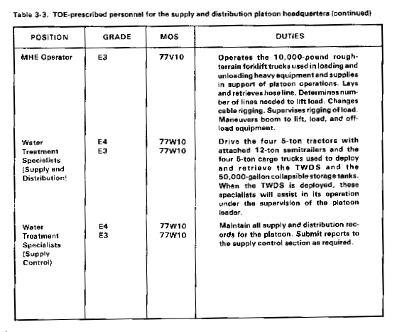
Your most valuable resources are your soldiers. To use them effectively, you must know their duties. Table 3-3 lists TOE-prescribed personnel of your section by position, grade, MOS, and duties.
This paragraph implements STANAG 2885 (Edition One). |
LAYOUT
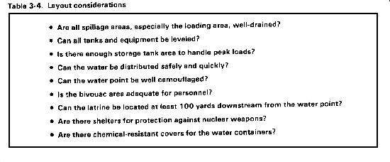
After a general operating area for the company is designated by battalion headquarters, your company commander may ask you to assist in reconnaissance of the area to determine the best location for your platoon. Once the site has been selected, you and your personnel must establish operating areas for all elements of the platoon. It is your responsibility to develop a layout plan. Some important points to consider in establishing your operating areas and setting up your equipment are given in Table 3-4. Site requirements for water points are presented in STANAG 2885.
According to the STANAG, the site should meet the following requirements or be capable of development to these:
- Easy and short access to and from a main route. One-way traffic past the water point.
- Waiting area for vehicles near the entrance to the water point, preferably with natural cover.
- A double width road opposite the filling points so that the vehicle being filled does not block the circuit.
- Well-drained hardstandings at the stand pipes.
- Ground with good, natural drainage, if possible at a sufficient slope to enable deliveries to be made by gravity from tanks to vehicles and from sedimentation tanks to sterilizing tanks if both are being used. The site should include even and nearly level spots where tanks can be erected without too much excavation. Where sites permit, pumping from the purification equipment to the vehicles thereby bypassing the requirement for storage tanks should be used if possible.
OPERATIONS
A major function of the platoon headquarters is to supervise and direct the overall operation of the platoon. You and your water treatment supervisor must assume these responsibilities. Some of these operations are described below.
Defense
Prepare your personnel to respond to ground and air attacks. Supervise the establishment of the unit defense while subordinate elements are preparing to occupy their designated areas.
Camouflage
Supervise camouflage activities once unit elements have established the defense and their operating sites. See FM 5-20, Chapter 8, for details about camouflage activities.
Capabilities
Make sure the necessary supplies are available to get the job done. Brief the company commander on the overall capability of the platoon. You should emphasize personnel strength and equipment availability.
Sanitation
Ensure that proper sanitation procedures are followed and that field sanitation standards comply with Army regulations and policies. For more information on field sanitation operations, refer to FM 21-10 and AR 40-5, Chapter 7.
Coordination
Once the supply platoon is operational, the platoon headquarters must coordinate and monitor operations performed by platoon personnel. To do this, you and your water treatment supervisor must--
- Assign tasks to the sections as required.
- Coordinate activities with supported units to ensure that the mission is accomplished and correct procedures are used.
- Ensure that plans and operations are carried out according to correct operating procedures.
Reports
Water point personnel submit daily reports to platoon headquarters on water distribution to using units. They use DA Form 1714-R (Daily Water Distribution Log) for this purpose. Headquarters personnel then consolidate the DA Forms 1714-R and submit a DA Form 1717-R to the supply control section. This summary should be analyzed to detect any unusual consumption of water by using units. DA Form 1717-R (Water Point Inspection Report) is completed regularly by representatives of the command surgeon who check the chlorine and bacteria content of the water and the sanitation of the water point. Appendix A shows samples of these forms. Blank forms suitable for reproduction are in FM 10-52. Reproduction of the forms on 8 1/2-by 1l-inch paper is authorized. Each reproduction must include the form number, the form title, and the date of the form. The forms are designed to coordinate the operation of widely separated water points. They also help to safeguard water quality, improve efficiency of water treatment, and decrease equipment maintenance. The forms furnish supply data for higher headquarters.
Supply control section personnel must review all forms, reports, and records for conflicting information, omissions, and other errors. They must correct all errors, distribute documents according to FM 10-52, and maintain records according to AR 340 series and local requirements.
Section V
SUPPLY SECTION
This section is for the water treatment supervisor.
MISSION
Each supply and distribution platoon has two supply sections. Each supply section can store up to 400,000 gallons of potable water at up to four locations. (Thus, total storage capacity of the company is 1,600,000 gallons.) Each section can store part of the command water reserve stock (maximum 400,000 gallons) and operate a direct support issue point.
PERSONNEL
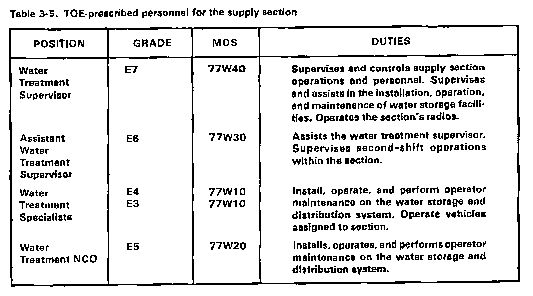
Your most valuable resources are your soldiers. To use them effectively, you must know their duties. Table 3-5 lists TOE-prescribed personnel of your section by position, grade, MOS, and duties.
STORAGE FACILITIES
Your section's duties in water supply operations include using the collapsible bulk water storage tanks and storing part of the command water reserve stock. Storage facilities should be large enough to meet daily peak demands. This will eliminate long waits at the water point by consumers. The 50,000-gallon collapsible tank is the standard tank available. The tanks are filled with chlorinated water. Water is rechlorinated when water is pumped from the tanks. Other storage considerations are described below.
Drainage
If drainage at storage and distribution sites is poor, several problems can occur. Leaks and spills from tanks, trucks, treatment units, and distribution systems may keep the area wet and muddy. Vehicles may get stuck in the mud. Standing water increases the risk of disease by providing breeding sites for mosquitoes and other insects. During cold weather, water may freeze and cause a safety hazard. Avoid these problems by planning for good drainage at each site. Be sure drainage is directed downstream from the water point.
Traffic
There will be many vehicles coming to and going from the water point. Provisions must be made for this traffic. For more details, see FM 10-52.
WATER STORAGE AND DISTRIBUTION SYSTEM
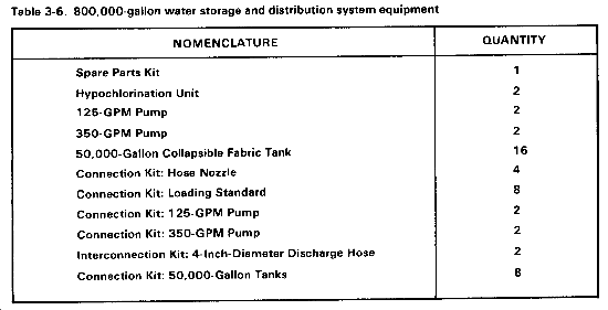
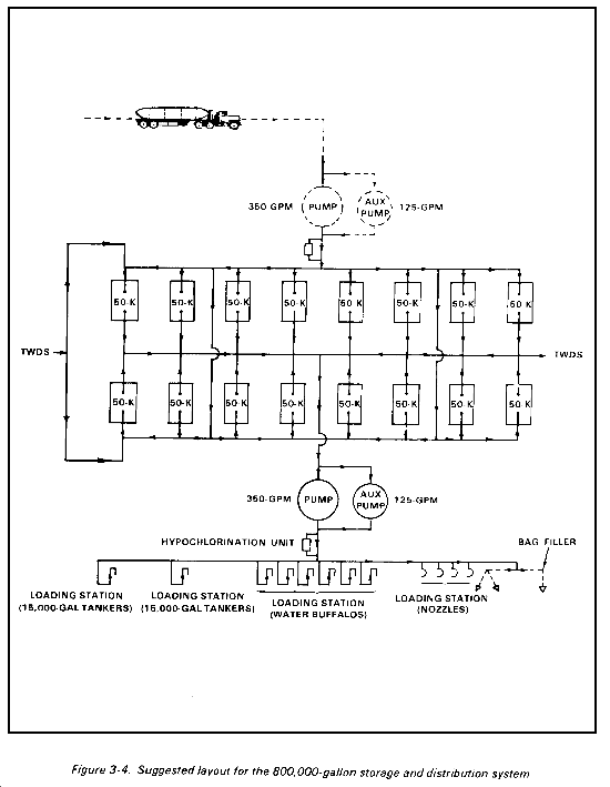
The 800,000-gallon water storage and distribution system consists of the equipment listed in Table 3-6. The manner in which you lay out this equipment will be largely determined by the terrain and the mission. The company SOP and AMTP should provide plans on how the system should be used. A suggested layout is in Figure 3-4. This is not the only possible arrangement. Any unit that can operate this distribution system can develop an arrangement to fit unit needs. Equipment should be dispersed but not so much that it is difficult to protect against terrorism and sabotage. The most serious threat you will face will not be having your site destroyed by fire or attack, but by having an infiltrator poison your water. For more details on the 800,000-gallon water storage and distribution system, see TM 5-4320-228-13&P.
50,000-Gallon Collapsible Tank
The 50,000-gallon collapsible tank is part of the system. It has a hose and valve assembly to help transfer water. This assembly consists of a 4-inch, wire-reinforced hose assembly (10 feet long) and a 4-inch gate valve. The female end of the 4-inch hose assembly is connected to the 4-inch elbow fitting of the filler/discharge assembly on the tank. The male end of the hose assembly is coupled to the 4-inch gate valve. The 50,000-gallon collapsible tank is used to store potable water. Tanks can be grouped in modular units or deployed separately, depending on the terrain. The site is prepared by an engineer unit using scoop loaders or by civilian labor or your personnel using a front loader or backhoe. The site should be sloped 3 to 6 inches toward both the fill port and manifold end of each collapsible tank. Do not setup the tank on an incline. If you do, the tank will start to roll when you fill it. If that happens, the only thing you can do is get out of its way. Setup two posts, one on each side of the tank, and run a string from one post to the other. The string should be 5 feet 8 inches from the ground. Do not fill the tank above this line or it will burst. Before moving from one place to another, empty the tanks. For more details on the tank, see TM 5-5430-210-12.
Hypochlorination Unit
The hypochlorination unit chlorinates water automatically before it is distributed. Chlorination destroys bacteriological contaminants. However, it does not neutralize chemical or mineral contaminants. Make sure that periodic bacteriological or chlorine residual tests are performed to monitor water quality. Acceptable levels of chlorine residual will be set by the theater or corps surgeon. Automatic operation of the hypochlorination unit ensures that during periods of changing flow, each gallon of water will receive the same amount of chlorine. This automatic operation is achieved by linking the operation of a water meter through a pilot valve to a hydraulically controlled hypochlorinator. This regulates the amount of chlorine injected into the water passing through the unit. As the flow of water through the meter changes, the amount of chlorine injected into the water also changes. The hypochlorination unit has a pressure-regulating valve that maintains a pressure of at least 10 psi. This ensures proper operation of the hypochlorinator. The unit can automatically treat from 2 to 400 gallons of water per minute. A range-adjusting valve is attached to establish maximum accuracy. The range-adjusting valve should be installed at its maximum setting of 400 GPM and then turned down depending on results of tests for chlorine residual. The hypochlorination unit is skid-mounted and portable. It can be manhandled into position by three soldiers. Quick-disconnect coupling valves enable hookup to the hose network.
350-GPM Pump
This pump draws water from the 50,000-gallon collapsible tanks and pumps it through the hypochlorination unit to the loading stations. If maximum RPM are not exceeded, the unit can be operated indefinitely. The unit does not have the ground rod and cable like the 350-GPM petroleum pump. The assembly should be pulled by a vehicle only when making short positioning moves in the immediate area. It is not designed to be towed in a convoy or on a cross-country move. For such a move, a 5-ton cargo truck or a flatbed trailer must be used. A forklift is needed to load and off-load the assembly. For more on the 350-GPM pump, see TM 5-4320-226-14 and FMs 10-20 and 10-69.
125-GPM Pump
This pump serves as an auxiliary to the 350-GPM pump. The pump is driven by a 3-horsepower engine. At an engine speed of 3,600 RPM, the pump delivers 125 gallons of water per minute against a head or elevation gain of 50 feet. The pump is portable and skid-mounted. It can be moved over short distances manually by lifting the ends of the pump frame. See TM 5-4320-208 12&P for more on the operation of this pump.
Section VI
DISTRIBUTION SECTION
This section is for the distribution section chief.
MISSION
The mission of the distribution section is to lay, operate, and retrieve 10 miles of collapsible hose line. This hose line is part of a TWDS. Each section also operates the water distribution points along the TWDS.
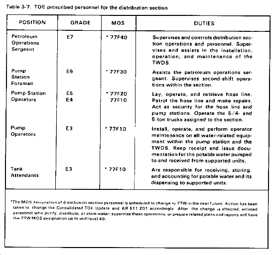
Your most valuable resources are your soldiers. To use them effectively, you must know their duties. Table 3-7 lists TOE-prescribed personnel of your section by position, grade, MOS, and duties.
Your section provides GS water transfer between storage facilities and operates up to two DS water points along the TWDS. In an arid or a hot region, the lack of fresh surface water and increased water use put great demands on the distribution system. If threat forces are able to disrupt water distribution operations, they may be able to significantly affect future operations. The distribution of water has to be closely controlled. Do this by scheduling. In order to set up the distribution schedule, you and the operations officer at the water supply branch of the water supply battalion need to work together. To plan your distribution, you need the name and location of units to be supported as well as the amount of water required. After you have this information, plan on how to get the water to the customer.
TACTICAL WATER DISTRIBUTION SYSTEM
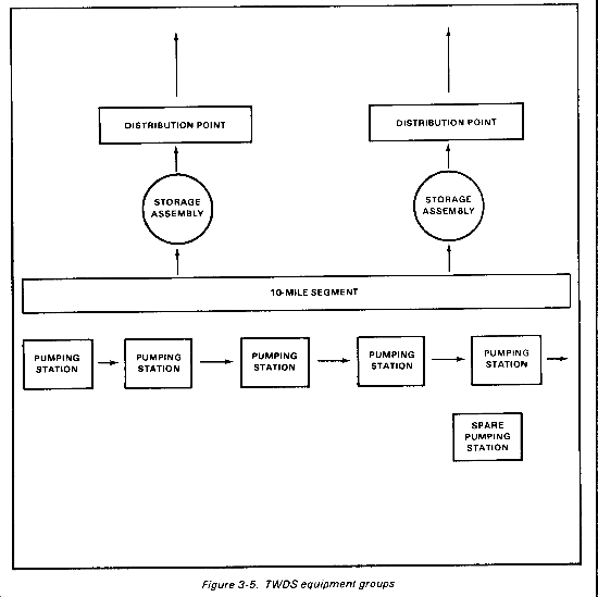
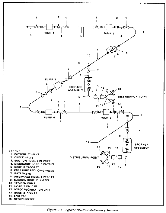
The TWDS is a 10-mile segment of hose line, storage assemblies, pumping stations, and distribution units used to transport and distribute potable water throughout the theater of operations. One TWDS can be joined to others to extend distribution capabilities. Your company has two TWDSs. However, your company can be augmented by as many as six TWDS teams. When the system is fully augmented, you can operate the system up to 80 miles. The TWDS has four equipment groups. They are shown in Figure 3-5. The TWDS is intended for use with potable water only. If brackish or contaminated water gets into the TWDS, it will contaminate the system. At full performance, the TWDS can move 600,000 gallons of water per day. This is the same as 10 trips of 10 tank trucks in the same period. A typical TWDS installation is shown in Figure 3-6. The two storage assemblies, the two distribution points, and the pressure-reducing valve may not be needed. Do not use the TWDS at temperatures below freezing. To do so will damage the TWDS. The TWDS can be unpacked, set up, and operating within 48 hours after delivery to the deployment site. Details on the TWDS are in TM 5-4320-303-10.
TWDS SITE SELECTION
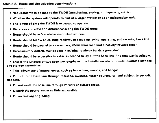
Before installing the TWDS, study the terrain. Examine and compare charts, contour maps, and photographs. Determine the general route for the TWDS hose line. The general locations of the pumping stations will be determined by the terrain. Establish the distribution points where the hose line passes through areas of large troop concentrations. Take full advantage of natural cover and the most level and accessible route. As a rule, plan the route near and parallel to a road. This will ease the job of transportation, assembly, inspection, operation, and maintenance. Plan to have enough crossing guards to protect the hose line where vehicles must cross it. Avoid routes along stream banks or through ponds or marshes. Floods could disrupt the hose line or make maintenance difficult. Lay out the hose line on firm, dry, level ground beyond any drainage ditches and parallel to a roadway. Do not lay the hose line on areas of exposed rock. The abrasive effect of rubbing against rocks will cause hose line damage and possible failure. Select a route based on the considerations in Table 3-8.
TWDS INSTALLATION
Install the pumping stations before you lay the hose line. The distribution points and the storage assemblies have to be installed in conjunction with each other.
Pumping Stations
After determining the best route for the hose line, determine the sites for the pumping stations. The first, or lead pumping station, should be located as near to the water source as possible. The site selected should be level with good drainage. You should take advantage of natural camouflage. The time required for site preparation will depend on terrain, the expected duration of the operation, the expected enemy action, and the time and equipment available. At a minimum, the pumping stations require a reasonably level location on firm soil with good drainage. The boost pumping stations are intended to be spaced at approximately 2-mile intervals along the hose line route. This spacing is adequate if the hose line route is reasonably direct and the terrain covered is level or gradually rolling with an elevation gain of no more than 50 feet from one pumping station to the next. If there is a hill higher than 100 feet or if the next pumping station is more than 50 feet higher than the previous pumping station, the spacing between pumping stations must be shortened. Also, you may have to install one or more pressure-reducing valves. A graphical method of locating pump stations and pressure-reducing valves is explained in TM 5-4320-303-10.
Pressure-Reducing Valve
The TWDS includes a pressure-reducing valve. The valve is for use if the hose line route includes a hill with a descent that causes buildup of excessive pressure (greater than 150 psi working pressure) at the bottom of the hill or if there is an elevation loss of more than 75 feet from one pumping station to the next. The pressure-reducing valve protects the hose line and fittings from excessive pressure that could rupture components. It also protects the pumping stations from receiving a suction pressure greater than 120 psi. If water with a pressure greater than 120 psi arrives at the suction port of a boost pumping station, the station will automatically begin to slow down to maintain a discharge pressure of 150 psi. The TWDS pumping stations are designed to run at normal operating speed. Slower speeds are less efficient. To determine whether you need to install a pressure-reducing valve and where to install it, do the calculations in TM 5-4320-303-10.
Other Components
Once the locations for the pumping stations have been determined, the trailer-mounted pumps can be installed. See TM 5-4320-303-10 for installation procedures. The TWDS includes two storage assemblies. They may not be required depending on the TWDS mission. If there is a requirement to use one or both of the storage assemblies, they can be located at any suitable site along the hose line route. See TM 5-4320-303-10 for points to consider in site selection and for preparation procedures. Distribution points may not be required. Distribution points, if required, must be used in conjunction with a storage assembly. The distribution point components should be unpacked where they will be used. The distribution point components include one 125-GPM pump. The pump should be unpacked only if required and then only at the distribution point site.
10-Mile Segment
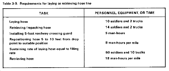
The 10-mile segment includes all other components necessary to install and operate the TWDS. This equipment group includes 500-foot lengths of hose line (in flaking boxes), a sling assembly, suspension kits, roadway crossing guards, pressure-reducing valve, suction hose assemblies, and miscellaneous fittings. This group also includes the displacement and evacuation kit, a packing kit, a repair kit, and the spare parts crate for the TWDS. The best way to unpack and install the 10-mile segment is to use the area around the lead pumping station site as the staging area for the unpacking operation. Components that need not be installed to operate the TWDS and all crating materials should be retained here. The hose line is let out from the rear of a moving truck and then physically moved to a position 5 to 10 feet from the road. No more than four flaking boxes (2,000 feet of hose line) can be loaded onto a 2 l/2-ton flatbed truck. Flatbed semitrailers may also be used. Up to 16 flaking boxes (1.5 miles) stacked four high can be loaded on the semitrailer. The hose line is deployed from the side of the vehicle. The 500-foot lengths of hose line are connected using victaulic couplings on the leading end of the hose line lengths. At all other connections, a swivel joint must be installed. To install the swivel joints, use the victaulic coupling on the leading end of the hose line length and an additional victaulic coupling to connect the swivel joint to the trailing end of the next hose line length. Make sure no dirt or other debris is in the hose sections or couplings. Any bends or kinks in the hose line must be straightened. The recommended speed for laying hose is about 3 miles per hour. Speed will vary depending upon the terrain, available personnel, and how far hose must be moved. The hose must not be left exposed on any roadway or track which will be traveled by other vehicles. Due to its lightweight, thin-wall construction, the hose line is easily damaged by rough handling, abuse, or abrasive contact with rocks. Table 3-9 lists personnel and equipment requirements for laying or retrieving hose line.
Roadway Crossing Guards
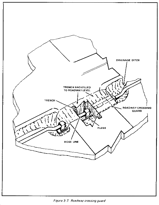
Sometimes the hose line must be laid across a roadway or railroad. The hose should be laid under an existing bridge or through an existing culvert. The leading end of the hose may be pulled through the culvert with a rope. If no bridge or culvert is usable, roadway crossings may be constructed using the roadway crossing guards provided. The hose line must never be buried unprotected. The weight of the fill would collapse the hose, and any sharp rocks in contact with the hose would cause a puncture. A plank should be nailed to the bottom of the guard for greater hose protection. It may be necessary to lay the hose under a railroad bed. Dig a tunnel beneath the gravel of the railbed, and nail a plank to the bottom of the guard. Do not lay the hose directly in the trench or railbed. The shifting gravel will gradually damage the hose. Install the roadway crossing guards as shown in Figure 3-7.
Suspension Kits
Aerial suspensions are the most effective and readily installed means of crossing streams and deep gaps. The displacement ball must be able to move freely through the hose line. For wide crossings, a suspension bridge should be built to provide a flat floor which will support the entire hose line length and to eliminate bends which would occur if suspension cables were used. If an actively used bridge is available, the hose line may be installed on it. Before you do so, check with the engineers to ensure the bridge is capable of supporting the hose line and its contents. The hose line should be secured outside the bridge structure. Crossings must be above flood stage. Each hose line suspension kit provides materiel for one 300-foot-wide crossing or two shorter crossings. Additional materials for the construction of suspension bridges, such as timber, bolts, and nails, are not included in the kit. They must be obtained locally.
TWDS OPERATION
Do not completely install the TWDS before you begin to operate it. Instead, fill and purge the hose line so that you can begin to distribute water as soon as possible. This will anchor the line and also help you to detect flaws in the system. The line must be anchored immediately because high winds will blow it about.
Pumping Stations
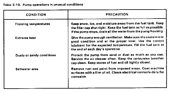
When you start the TWDS, make sure that operators at the pumping stations and storage assemblies can communicate with each other and the crews laying the hose line. Have operators monitor the advance of the water column. They should report anything unusual or problems as soon as they occur. Have operators monitor the suction and discharge pressures at the pumps. Report low suction or high discharge pressure. Correct problems at once. Make sure anyone who is within 21 feet of an operating pump wears hearing protection. Table 3-10 has tips for operating the pumps in unusual conditions.
Storage Assemblies
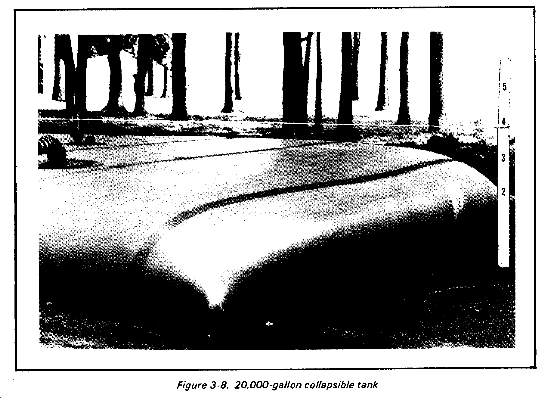
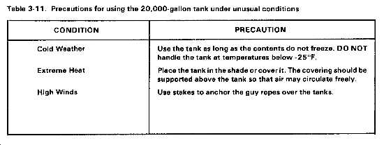
The 20,000-gallon collapsible tank (Figure 3-8) is the standard storage tank. Have storage assembly operators announce the start and end of tank-filling operations. They should tell the pumping station operators when a tank is filled. Pumping station operators can expect a reduction in hose line pressure. Care should be taken not to fill storage tanks at a rate that will cause downline pumping stations to reduce speed. Table 3-11 has precautions to be followed when operating under unusual conditions.
Distribution Points
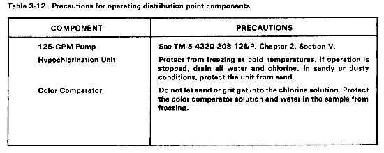
Make sure the water goes through the hypochlorination unit before it goes through the branching hose network. The major components of the distribution point are the 125-GPM pump, the hypochlorination unit, and the color comparator. Table 3-12 has some tips for operating them in unusual conditions.
10-Mile Segment
The most important part of operating the 10-mile hose line is to keep downstream hose line pressure under 155 psi and pressure at the next pumping station between 20 and 120 psi. The best way to do this is to adjust the pressure-reducing valve so that the outlet pressure is as high as possible without danger of exceeding the upper pressure limits. Once the valve is adjusted properly, it will automatically control the downstream pressure regardless of inlet pressure or changing flow rates. There are some precautions you should take in unusual situations. When operating at freezing temperatures, protect the unit from rain, snow, and moisture. This will help to prevent couplings, stopcocks, and adjustments from freezing. If the pumps stop, disconnect the valve from the hose line and drain all water. When operating in extreme heat, cover the unit to shade it from the sun. When operating near salt water, remove any rust or aluminum oxide formations and paint the exposed surface. Protect machine surfaces with a film of oil. Avoid removing the anodized coating from aluminum fittings.
TWDS MAINTENANCE
Make sure the TWDS is regularly and systematically inspected. Note defects discovered during operation. Have them corrected as soon as operations stop. If you find a defect which would damage equipment during continued operations, stop operations at once. Inspect the system daily for leaks while it is operating. Leaks are caused by improper installation, faulty gaskets, damaged sealing surfaces, and defective hoses or fittings. Before you try to repair a leak, isolate the leaking area. You can do this by installing hose clamps on either side of the leak or by closing an appropriate valve. If it will take a long time to repair a leak, you may have to stop operation of the TWDS. For example, if you have to replace a damaged section of the hose line, shut down the pumping stations until the repair is finished. This will prevent downline pumps from running dry, which could damage them. However, you can replace a faulty gasket or correct an improper installation while the TWDS operates. Connections should be inspected for improper installation before disconnection. Gaskets can deteriorate or become damaged through normal wear and tear. Fittings which include gaskets should be checked for serviceability. Nicks, dents, or burrs on the sealing surface of many parts can also cause leaks. Use emery paper or a file from the repair kit to smooth the sealing surface. Take care not to make any more scratches or marks while repairing the surface. If you cannot smooth the surface, replace the defective fitting or hose assembly. When repair is completed, remove the hose clamps or open the valves at once. Make sure the repair procedures have corrected the leak. Defective hoses or fittings on shorter hose assemblies that cause leaks must be replaced. Longer hose line lengths can be repaired by replacing defective fittings or by removing the damaged section of hose line and splicing the ends together.
Section VII
MAINTENANCE SECTION
This section is for the wheeled vehicle maintenance technician.
MISSION
The mission of the maintenance section is to provide the personnel and equipment to perform unit maintenance on equipment. This equipment includes vehicles, generators, MHE, TWDSs, 800,000-gallon water storage and distribution sets, pumps, and compressors.
PERSONNEL
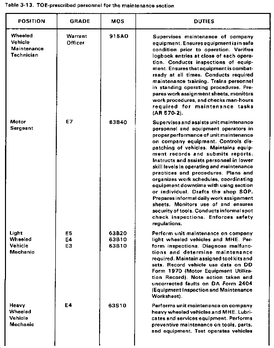
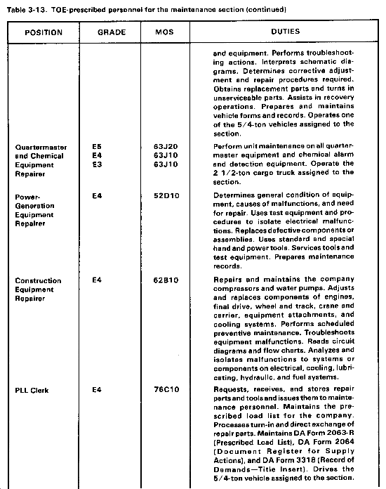
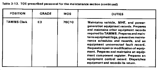
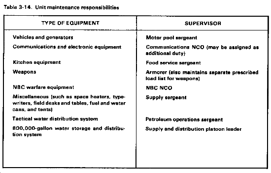
Your most valuable resources are your soldiers. To use them effectively, you must know their duties. Table 3-13 lists TOE-prescribed personnel of your section by position, grade, MOS, and duties. Supervisors are responsible for the maintenance of all assigned equipment. Table 3-14 identifies who is responsible for various pieces of equipment.
OPERATIONS
Maintenance operations are divided into three levels: unit, intermediate (direct and general support), and depot. (See AR 750-1, Chapter 4, for details.) Your section is responsible for unit maintenance. Your primary objective is to ensure mission capability of equipment. You must make sure PMCS is performed regularly. At times your maintenance capabilities may be limited due to lack of time, tools, and repair parts. Maintenance your section cannot perform is done by a support activity through higher headquarters. For information on effective maintenance management, see DA Pamphlets 738-750 and 750-1 and FM 29-2.
SETUP AND CLOSEDOWN
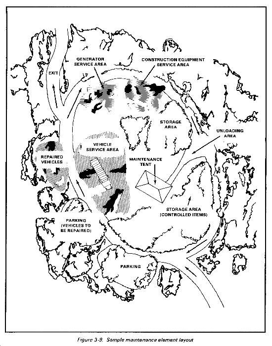
Field situations seldom allow you to operate under ideal conditions. However, the areas selected for maintenance must be centrally located, be on or near a good road, provide concealment, be easily defended, and be relatively hard-surfaced and well-drained. To set up a maintenance section in the field, you need to develop a layout plan, pitch tents, position equipment, and organize for operations. A sample site layout plan is shown in Figure 3-9. See TM 10-8340-211-13 for information on pitching and striking tents. When it is time to move, the commander will issue a warning order and then an operation order. You must then close down maintenance operations. Assign a detail to load supplies and equipment on trucks and strike the tents. Perform before-operation maintenance checks and services. Make sure vehicle operators know their responsibilities while on the march and when in the new bivouac area. See FM 55-30 for more on movement.
FUNCTIONS
The primary functions of the unit maintenance element include maintenance by operators and unit mechanics, repair parts operations, tool maintenance and accountability, record keeping, dispatching, and recovery and evacuation of disabled equipment. These are described below.
Operator and Crew Maintenance
Equipment operators must perform daily PMCS on their equipment. They also make minor repairs identified by technical manual allocation charts as being within their capabilities. Operators also assist in lubricating equipment according to lubrication orders. While operating equipment, the operator and crew should be alert for unusual noises or odors, abnormal instrument readings, steering irregularities, or other indications of malfunction. After-operation service should include checking fluid levels, tire pressures, batteries, and electrical wiring. See FM 55-30, Appendix U, for a sample vehicle inspection checklist.
Unit Maintenance
Deficiencies discovered before, during, and after operation which are beyond the operator's capability become the responsibility of unit mechanics. Maintenance performed by unit mechanics includes inspecting, servicing, lubricating, adjusting, and replacing parts, minor assemblies, and subassemblies. The scope of repairs they make is specified in equipment TMs. Repairs beyond the capabilities of your mechanics are the responsibility of higher-level maintenance activities. Normally, your section delivers the unserviceable equipment to the supporting maintenance activity. If this is not possible, you may request that a maintenance support team be provided.
Repair Parts Operations
You are authorized a PLL or combat PLL to support daily maintenance operations. Usually, the PLL is for a prescribed number of days of supply based on the average customer wait time. You supervise the PLL clerk and make sure the list is set up and maintained according to requirements in DA Pamphlet 710-2-1 (TMs in the 38-L32 series if your unit is automated). The PLL clerk requests parts based on supervisors' anticipated needs. Supervisors at each level must anticipate and plan for materiel needs. The PLL clerk requests parts by national stock number. To ensure requests are submitted in a timely manner, find out the average maximum lead time for items requested. Make daily requests SOP to prevent an accumulation of requests and to help ensure continuous supply. Specify procedures for establishing PLL levels, for using priority designators, and for requesting follow-ups and reporting delays.
Tools Maintenance and Accountability
Establish an effective control system, and inventory tools regularly. Account for and replace lost, damaged, or destroyed tools according to AR 735-5. See TM 9-243 for information on use and care of tools.
Automotive tool kits. Issue by hand receipt an automotive tool kit to each mechanic. The tool kit contains common tools such as wrenches, pliers, hammers, drifts, punctures, chisels, files, and gages. Each mechanic is responsible for ensuring that assigned tools are properly maintained and stored when not in use. Establish a secure tool storage area.
Unit shop equipment. You are authorized a set of common tools and equipment to perform your unit maintenance mission. This equipment set is usually mounted on a secured vehicle. One side of the vehicle can be used for storing tools and test equipment, leaving the other side to store key repair parts. This setup will make displacement quicker and on-site repair easier. Assign a tool keeper to maintain a tool sign-out register. Make sure equipment is returned at the close of each working day.
Records
DA Pamphlet 738-750 has specific instructions on the preparation and use of maintenance system forms. See Table 3-15 for key records that you will use. The three types of records are operational, maintenance, and historical. Operational records are used to control operators and equipment, to plan for maintenance operations, and to make best use of equipment. Maintenance records control maintenance scheduling, inspection procedures, and repair work loads and provide a uniform method of recording corrective actions. They are used to determine equipment readiness and reliability and to determine use and logistic requirements. Historical records are permanent documents formalizing the receipt, operation, maintenance, and disposal of equipment.
Dispatch
Dispatch procedures apply to vehicles, generators, forklifts, engineer equipment, and other items the commander designates. The operator contacts the dispatcher with a vehicle requirement. The dispatcher designates a vehicle. The operator is responsible for maintenance checks and services before, during, and after operation of the item. Records are kept on all services performed and the mileage or hours related to use of the item.
Recovery and Evacuation
It may become necessary to recover equipment which becomes disabled in a location away from the motor pool. Your soldiers may be unable to repair the disabled equipment. You must make arrangements to evacuate the equipment and have it serviced elsewhere. To prepare for recovery, consult TMs for the weight of the item and for other data. Reconnoiter the area to determine the best method of anchoring the wrecker vehicle. If the unit cannot recover an item, request evacuation by the supporting maintenance activity. FMs 20-22 and 21-305 provide guidance on vehicle and equipment recovery and evacuation.
|
NEWSLETTER
|
| Join the GlobalSecurity.org mailing list |
|
|
|


