CHAPTER 5
AIRCRAFT RECOVERY
This chapter contains information on approaches and recoveries to amphibious ships (LPH, LHA, and LHD) and aircraft carriers (CV and CVN) after missions. It also covers safety considerations; single-spot ship operations are covered in Appendix D.
Once released by mission controllers, aircraft entering the ship's control area will switch to the AOCC/HDC frequency for further clearance to the marshal pattern. Adjustments to the landing order may be made to accommodate aircraft materiel conditions, fuel state, and hung ordnance. Flights will check in with AOCC/HDC when they enter the control area or when directed by other control agencies. These aircraft will provide the following information:
The aircraft call sign.
The position relative to the ship.
Altitude.
Fuel state (hours and minutes of lowest fuel state in flight).
Souls on board.
AOCC/HDC will respond with the following information:
The expected approach time.
Marshal instructions, if required.
Vectors, if required.
The estimated recovery time.
The altimeter setting, wind, weather, and BRC.
The time.
Other pertinent information.
Clearance into the control area.
Pilots will report "See you" when they make visual contact with the ship. AOCC/HDC will switch the flight to the PriFly frequency at 5 nautical miles (VMC).
a. Case I, Visual Descent or Approach (Helicopter). (See Figures 5-1 on page 5-3, 5-2 on page 5-4, 5-3 on page 5-5, and 5-4 on page 5-6.) Case I may be used when flights are not expected to encounter IMC anytime during the descent, break, and final approach. Weather minimums of 1,000 feet ceiling and 3 miles visibility are required in the control zone.
NOTE: During mixed aircraft operations, helicopters will enter the starboard Delta pattern which is located one mile to the starboard side of the ship at 300 feet and oriented on the BRC. (See Figure 5-1.) During mixed aircraft operations, the helicopter break altitude will not exceed 300 feet.
b. Case II, Controlled Descent or Visual Approach (Helicopter). Case II will be used during the day when weather conditions are such that flights encounter IMC during the descent but VMC of at least a 500-foot ceiling and 1-mile visibility exists at the ship. Positive control will be used until the flight leader or pilot reports that he has the ship in sight. AOCC/HDC will be fully manned and ready to assume control of Case III recoveries if the weather deteriorates below Case II minimums.
NOTE: Case II approaches will not be flown when Case III departures are in progress. Case III approaches will be used during marginal VMC.

Figure 5-1. Delta and Charlie patterns for helicopters
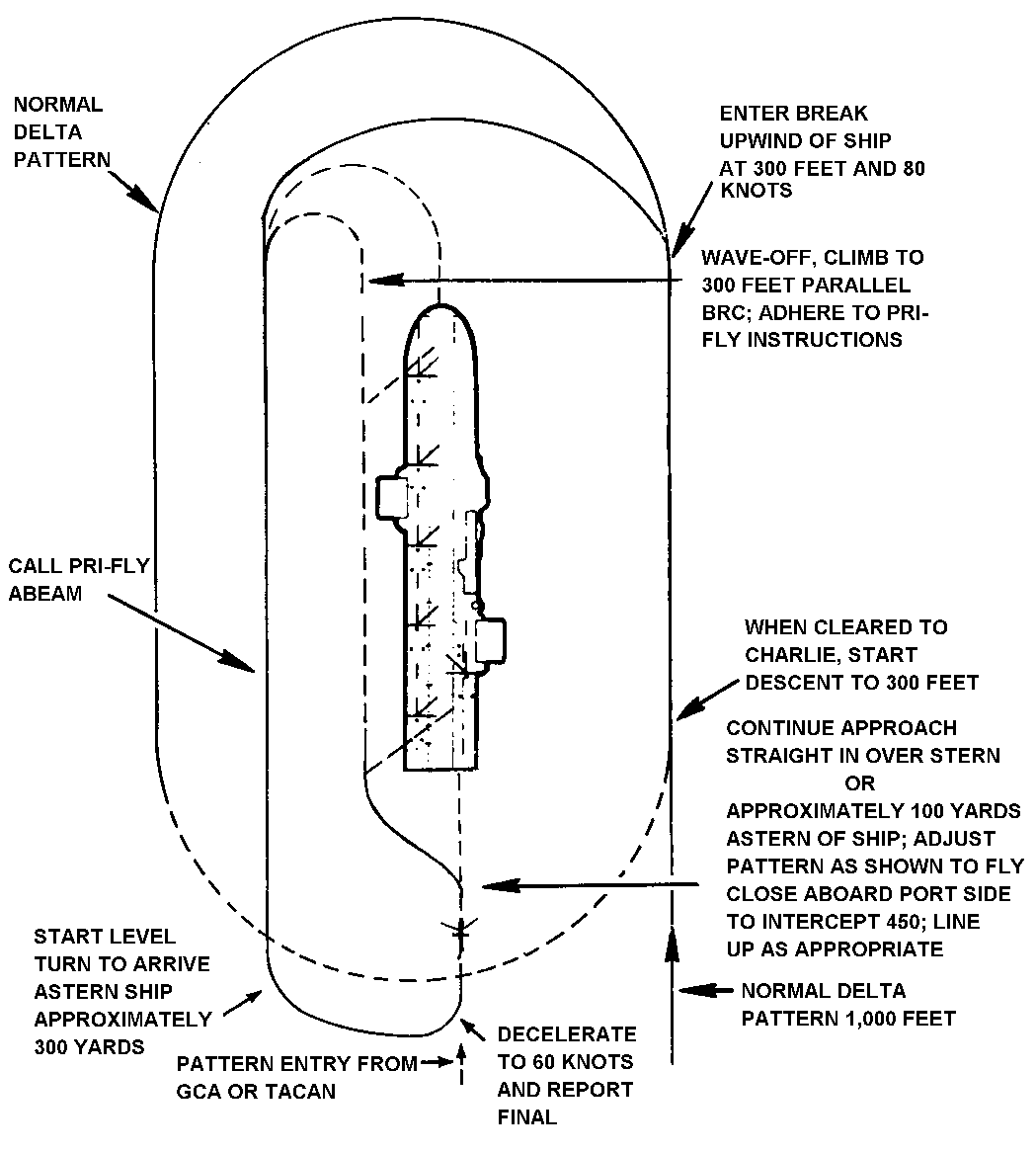
Figure 5-2. Helicopter night Case I recovery pattern

Figure 5-3. Helicopter recovery patterns for starboard side spots
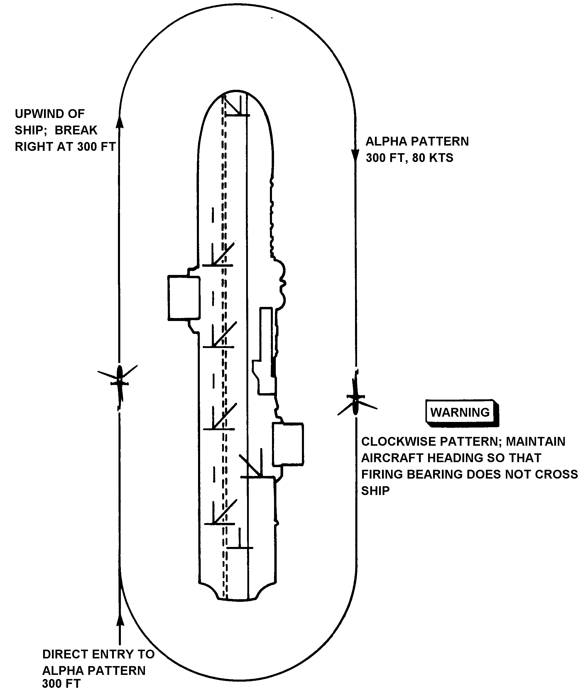
Figure 5-4. Alpha pattern--recovery of armed helicopters
c. Case III (Helicopter). (See Figure 5-5 on page 5-8.) Case III will be used when weather conditions at the ship are below Case II minimums. Unless modified by the ship's CO or OTC, Case III also will apply to night flight operations when there is no visible horizon. Case III formation recoveries are not authorized unless an aircraft experiencing difficulties is recovered on the wing of another aircraft. A straight-in, single-frequency approach will be provided in all cases. Formation flights by dissimilar aircraft will not be attempted except in extreme circumstances when no safer recovery methods are available. Precision radar will be used whenever available. The following procedures are mandatory for all Case III recoveries.
(1) LPH, LHA, and LHD marshal patterns. The assignment of marshal patterns depends on the topographical features, ships in formation, operational restrictions, and aircraft capabilities. The sky should be clear. While the following procedures are written for TACAN-equipped aircraft, these procedures can be adapted using other Army-specific navigation equipment (Doppler, GPS, INS, and so forth).
|
WARNING TACAN marshal two will not be used during mixed aircraft operations. |
NOTE: All bearings are relative to the BRC. All legs are two nautical miles long, standard rate turns.
TACAN marshal one--180-degree bearing at 7 miles, altitude as assigned.
TACAN marshal two--270-degree bearing at 7 miles, altitude as assigned.
TACAN marshal three--090-degree bearing at 7 miles, altitude as assigned.
|
WARNING Base altitudes for TACAN marshal patterns one, two, and three will not be less than 1,000 feet. |
NDB/TACAN overhead marshal--Overhead holding pattern on the 30-degree relative bearing, altitude as assigned (not less than 500 feet), 1 minute and a two nautical mile racetrack pattern, left-hand turns. See Figure 5-6 on page 5-9.)
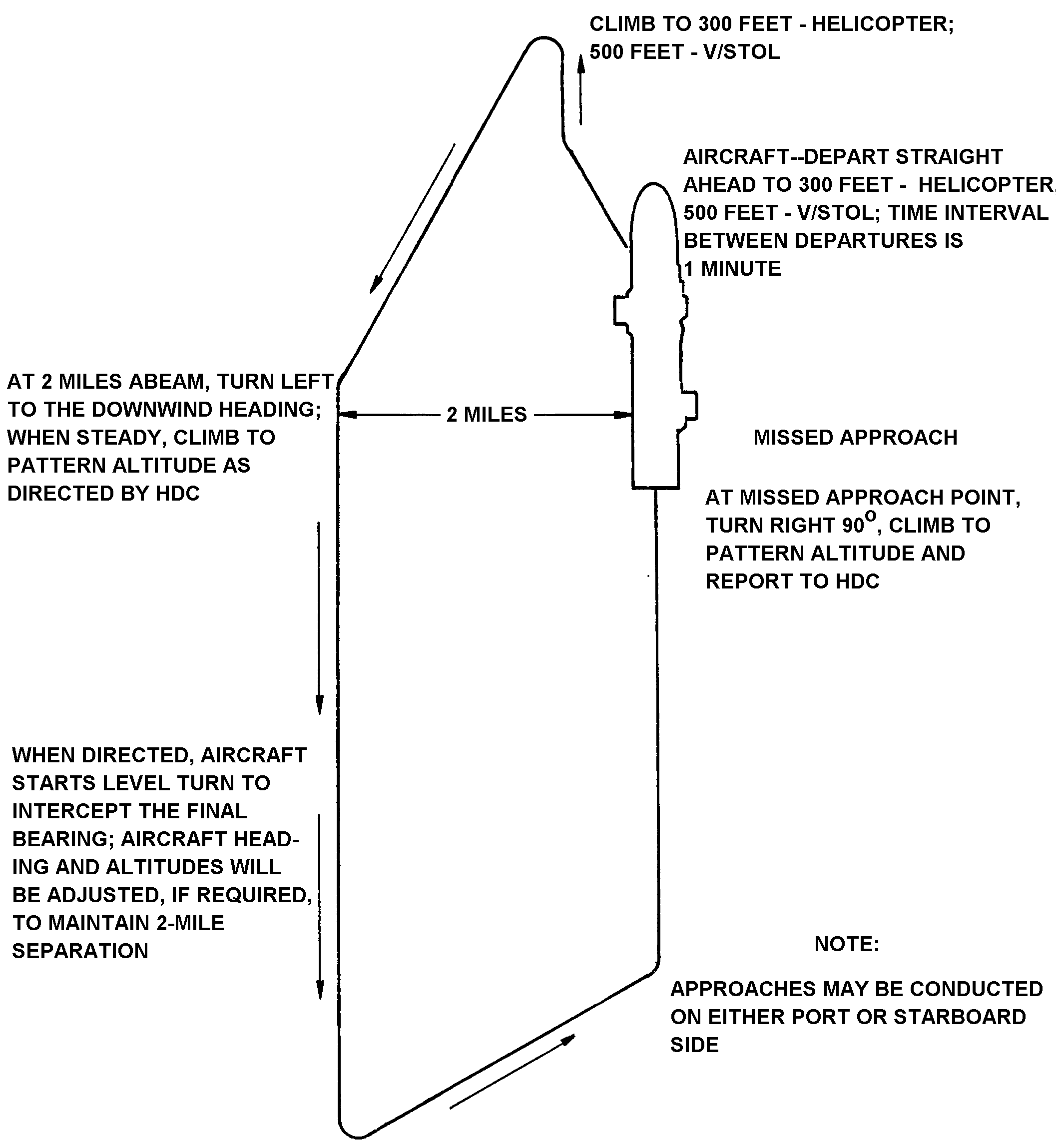
Figure 5-5. Case III carrier qualification pattern
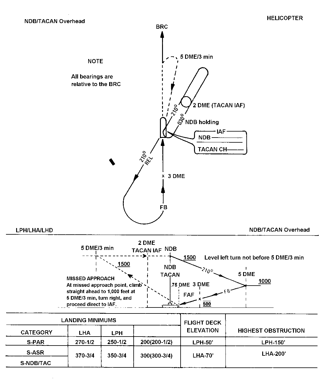
Figure 5-6. Approach chart (LPH, LHA, LHD NDB overhead)
(2) CV and CVN marshal patterns. Aircraft carrier marshal patterns differ from those for amphibious assault ships in the way they are numbered and the altitudes at which they are flown. The CV/CVN marshal stack starts at altitudes of at least 5,000 feet and at 20 DME on the 180 degree radial. Because these marshals are not practical for helicopters, the Army aviation unit and the ship's leadership must agree on a marshal stack altitude during the presail conference.
(3) Marshal altitude assignment. Altitudes in marshaling will be assigned in VMC, if possible. If one aircraft is having communications or navigation equipment difficulties, a formation of two aircraft may be assigned to the same marshal for a section approach. Otherwise aircraft will be separated vertically by a minimum 500 feet.
(4) Marshal airspeeds. Marshal airspeed will be based on holding airspeeds specified in the applicable aircraft NATOPS flight manuals.
(5) Approach instructions. AOCC/HDC will provide the following information to each aircraft before approach clearance is issued:
The new EAT.
The final control frequency.
The type of approach and outbound bearing (overhead approaches only).
NOTE: The assigned outbound bearing will be updated continuously during recovery to maintain a minimum of 20 degrees clockwise from the reciprocal of the final bearing (overhead approaches only).
Frequency and IFF changes.
(6) Marshal pattern departures. Weather conditions permitting, operational aircraft departing the marshal pattern will have a 1-minute separation. Pilots must adjust patterns to depart the marshal pattern at the assigned EAT. Deviations from the EAT will be reported to the marshal controller immediately so that adjustments can be made to the interval for the following aircraft. Descents from the marshal pattern will be at 90 knots and 500 feet per minute to the final approach fix. Helicopters will assume the landing configuration before passing FAF.
(7) Radar approach.
(a) Precision. When available, precision radar will be used to the maximum extent possible. The pilot will be provided heading and glide slope information on final.
(b) Nonprecision. When glide slope information is not available, aircraft on final will continue the descent to MDA after passing FAF. The final controller will provide the pilot with recommended altitudes and enough information to maintain accurate azimuth and safe altitudes until the aircraft reaches nonprecision minimums.
(8) Approach minimums. Approach minimums are shown on the ship's approach charts. The CO may increase these minimums if required by significant changes in operational capability such as decreased AOCC/HDC or proficiency of the embarked unit..
(9) Missed approach wave-off. Helicopters executing missed approaches will turn right 90 degrees, intercept the 5-mile arc, and arc right to reenter on the final bearing. If the deck is fouled or there are an excessive number of wave-offs, AOCC/HDC will direct all aircrews to proceed according to the last clearance and stand by for new instructions.
(10) Divert field. When a suitable divert field is available, aircraft will not begin an approach if the reported weather at the ship is below minimums unless the aircraft has enough fuel to proceed to the divert field in the event a missed approach is required.
5-2. LOST COMMUNICATIONS OR NAVIGATION AIDS DURING THE APPROACH
If communications or navigational aids are lost during the approach, the procedures outlined below will be followed.
During IFF, squawk according to ship's procedures.
During VMC, remain VMC and continue the approach using VFR lost communication signals and procedures.
During IMC or at night and only aircraft communications are lost, continue the approach. Try to contact the ship using the survival radio if time permits and safe aircraft control is not jeopardized. When visual contact with the ship is made, follow the signal procedures shown in Figure 5-7.
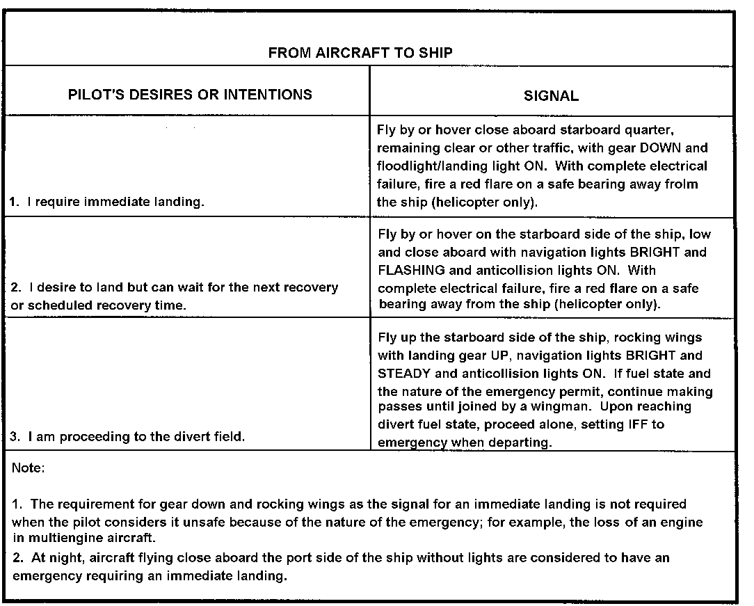
Figure 5-7. Visual signals during EMCON or lost communications
a. Complete Communications or Navigation Failure.
(1) The pilot of the signal aircraft may elect to continue the approach by dead reckoning to the MDA until at least 2 minutes have elapsed since the expected arrival time. The pilot will climb out on the final bearing until VMC is achieved or he reaches the emergency marshal altitude. He will fly the appropriate triangular pattern at altitude, conserve fuel, and expect join-up. The pilot will follow lead or, at his discretion, fly to a divert field fuel permitting. If below overcast, he will fly the DR search pattern to locate the ship. When visual contact with the ship is made, the pilot will follow the procedures shown in Figure 5-7.
(2) The pilot may elect to discontinue the approach. If so, he will climb on final bearing to VMC or emergency marshal altitude using the DR and follow the procedures shown in Figure 5-7.
NOTE: In the recovery procedure, an aircraft with inoperative navigation and/or communications equipment that is with or joined by an escort aircraft with operable navigation or communication equipment is handled as a single flight. The escort aircraft becomes the flight leader and normally communicates with the distressed aircraft according to standard procedures. The distressed aircraft assumes a position on the starboard wing of the lead aircraft. When the pilot of the lead aircraft has the ship in sight, he visually communicates a lead change. The distressed aircraft will complete a visual approach to a landing. The escort aircraft will enter Charlie pattern for a landing. If conditions preclude continued flight in the Charlie pattern, the escort aircraft will climb straight ahead on the BRC to one nautical mile DME or two minutes. Missed approach instructions will be complied with according to the applicable TACAN approach or as HDC/AOCC instructs.
b. Helicopter Emergency Marshal. An emergency marshal pattern provides an established procedure for aircraft experiencing lost communications to return to the ship during IMC. Pilots will be briefed on the emergency marshal pattern before initial takeoff. (These procedures presume that the TACAN azimuth and DME are operable.)
NOTE: TACAN marshal pattern 3 conflicts with the emergency marshal pattern.
(1) LPH, LHA, and LHD operations are unique in that helicopter final recovery times cannot be predicted because of mission status and the use of hot refueling. Therefore, an emergency marshal procedure must be established. This procedure will remain in effect throughout the aircraft event and will not have to be updated when the final recovery time of the aircraft is extended by hot refueling. The emergency marshal pattern for helicopters provides for the recovery of 24 individual helicopters experiencing lost communications or IMC.
(2) Each aircraft on the ship's air plan will be assigned an emergency marshal point. Radial, DME, EEAT, and altitude assignments are based on the assigned marshal point. The marshal point assignment will not be changed during the aircraft event except as requested by AOCC/HDC or the pilot and then only with the approval of both parties.
(3) The 24 marshal points are positioned on three TACAN radials and eight DME fixes at eight separate altitudes. The system provides lateral, vertical, and time separation. Radials are labeled A through C and are 45 degrees apart. Assigned radials are relative to the EEB.
(4) A helicopter experiencing lost communications during IMC will proceed outbound from the ship and climb or descend to the assigned emergency marshal altitude. It then proceeds directly to the assigned emergency marshal fix.
NOTE: During mixed operations, helicopters will cross at or above 2,000 feet.
(5) The appropriate IFF code will be squawked--mode 3, code 7700 for 1 minute, followed by mode 3, code 7000 for l4 minutes. The holding pattern is standard (right-hand turns) with the assigned DME being that point at which the outbound turn starts. The inbound turn starts at the DME fix plus two run. The pilot will maneuver the helicopter to be at the assigned DME fix on the assigned altitude at EEAT. At EEAT, he starts the descent to 500 feet and proceeds inbound to the five nautical mile DME arc. At the five nautical mile DME arc, the pilot turns left, and arcs clockwise to the EFB. He turns inbound on the EFB and starts the descent from 500 feet at the final approach fix (three nautical mile DME) to the minimum descent altitude. A missed approach will be according to the published TACAN approach.
NOTE: Helicopter airspeed throughout the emergency marshal pattern is 90 knots except during holding. During holding, maximum fuel conservation airspeeds will be observed.
(6) The emergency marshal pattern has two sets of EEATs. When 16 or fewer aircraft are launched, the pattern is repeated twice each hour. When more than 16 aircraft are launched, the pattern is repeated every hour.
c. Smoke Light Approach.
(1) This approach is used when available equipment does not allow normal procedures to be used. It also will be used when the ship cannot be acquired visually using normal procedures and ditching is imminent. Both the CO and the PC must agree to attempt the procedure.
(2) The aircraft is positioned 2 miles astern the ship and proceeds inbound (180 degrees relative bearing to the BRC). The aircraft descends at the pilot's discretion to 40 feet and 40 knots. Smoke or matrix lights are dropped every 15 seconds (or another prearranged interval), and the pilot is kept informed of the number of smoke lights in the water. The pilot at the controls follows the smoke lights up the ship's wake, adjusting his closure rate until he can see the ship.
d. Proximity to Land Masses or Other Control Zones. Emergency marshal patterns are designed for blue water operations. Close proximity to land masses or control zones will require modification of emergency marshal procedures because exact conditions cannot be predicted. The ship's air operations officer must assign emergency marshal patterns that do not conflict with other aircraft, existing obstructions, or other patterns in use.
e. Emergency Approach Procedures. If an emergency condition exists or the aircraft does not have enough fuel to comply with the assigned emergency marshal procedures, the pilot will squawk the appropriate IFF code, climb or descend to 500 feet, proceed to and intercept the EFB at the 5 DME, and proceed inbound. Upon noting the arrival of an aircraft not under positive control, the AOCC/HDC will clear all aircraft from the anticipated route of flight of the distressed aircraft.
If weather conditions are below Case II, particularly at night, a divert field or ship should be provided. The squadron commander and the air operations officer are jointly responsible for ensuring that aircraft performance data pertinent to diversion is available and understood by air control personnel.
a. Responsibilities.
(1) The ship's CO decides whether to divert the aircraft.
(2) At night and during IMC, the air operations officer makes the appropriate recommendations to the CO as to which aircraft should be diverted or when the aircraft should not be diverted for flight safety. During VMC operations, the air officer makes these decisions.
(3) The LSO makes timely recommendations to the air officer regarding diversions based upon unsatisfactory pilot performance or landing conditions.
(4) The pilot will inform PriFly when he reaches bingo state without divert instructions.
(5) If practicable, the air operations officer determines the condition of NAVAIDs, communications, and lighting at the divert field before the first night or IMC recovery.
b. Planning Considerations. The following factors must be taken into consideration when aircraft diversion is being planned:
Aircraft fuel state.
Range and bearing to the divert field.
Weather at the divert field (both current and forecast).
Status and availability of the divert field for the type of aircraft.
Available navigation assistance.
Ordnance restrictions.
Mechanical condition of the aircraft.
Condition of the flight deck.
c. AOCC/HDC Responsibilities. AOCC/HDC will be alerted when an aircraft is approaching diversion state and be prepared to take control of the aircraft when the divert order is issued. AOCC/HDC will--
(1) Advise the pilot of the name of the divert field and its magnetic heading and distance.
(2) Advise the pilot to check that the gear is up (if applicable).
(3) Instruct the pilot to shift to the control frequency en route.
(4) Provide the pilot with the latest available en route weather, the altimeter setting at the divert field, and the position from which divert was made.
(5) If operations are being conducted outside an ADIZ boundary, provide the pilot with the necessary ADIZ information. Advise the appropriate GCI site of the diverting aircraft's departure point, ADIZ penetration point, time of penetration, altitude, estimated time en route, destination, and any other pertinent information.
(6) Maintain a radar plot and radio monitor on the diverting aircraft for as long as possible and/or retain positive control responsibility for the aircraft until positive radar hand-off to the GCI, ARTCC, or another appropriate controlling agency.
(7) File a divert flight plan with the appropriate controlling agency. Ensure that similar information is provided to the pertinent air defense agency should an ADIZ penetration be necessary.
(8) Receive an arrival report for the diverting aircraft.
d. Pilot Responsibilities. After the pilot of the diverted aircraft lands, he will notify the ship by immediate precedence message.
The following actions will be completed in preparation for aircraft recovery:
a. The OOD will ensure that preparations for flight quarters are completed according to this manual. Operational checks of PriFly equipment, flight deck lighting, and optical landing aids normally will be completed before the beginning of air operations; which usually consists of manning the necessary stations.
|
WARNING H-53E aircraft create more rotor downwash than any other embarked helicopter. This downwash can cause damage to unsecured rotor blades; blow aircraft chocks, tie-down chains, and tow bars about the deck or overboard; and cause injury or death. |
b. Safe aircraft recovery operations require strict adherence to wind and deck limitations. The ship's CO may establish more restrictive limitations.
(1) Approaches.
(a) Initial contact. Flight leaders and/or aircraft commanders will report "see you" when the ship is in sight. At that time, AOCC/HDC will switch the flight to the land/launch frequency for PriFly control. Unless otherwise cleared by PriFly, flights will proceed and hold in the Delta pattern. (See Figures 5-1, 5-2, and 5-3.) The flights will plan their descent, break to meet the designated recovery time, and maintain an orderly flow of traffic into Charlie pattern.
(b) Standard Delta pattern. The Delta pattern is a VFR holding pattern established near the ship. Normally, the Delta pattern is a left-hand racetrack pattern around the ship. As shown in Figures 5-1, 5-2, and 5-3, it is oriented on the ship's heading, is close aboard the starboard side, and is flown at an optimum airspeed. During heavy traffic periods, additional Delta patterns may be used as assigned by PriFly.
(c) Helicopter starboard Delta. Normally, a holding pattern on the right side of the ship is a right-hand racetrack pattern that is oriented on the ship's heading at an assigned altitude (Figure 5-1).
(d) Charlie pattern. The Charlie pattern for all aircraft is a left-hand racetrack pattern on the port side of the ship. The upwind leg is a course that parallels the BRC. Unless otherwise directed by PriFly or AOCC/HDC, all aircraft will enter the Charlie pattern as shown in Figures 5-1, 5-2, and 5-3. The landing interval will be established or adjusted upwind so that it does not extend the downwind leg.
(e) Prep Charlie pattern. Aircraft cleared to Prep Charlie will conform to the normal Charlie pattern entry procedures. Once established in the pattern, they will conform to the racetrack pattern shown in Figures 5-1, 5-2, and 5-3 until PriFly clears them to land.
(f) Helicopter night Case I recovery pattern. The helicopter night Case I recovery pattern is a left-hand pattern on the port side of the ship. The pattern is extended downwind which allows the helicopter to complete the turn to final before starting the descent. The straight-in final approach is flown using the available visual landing aids such as SGSI, CAI Mod 2, and HAPI.
(2) Recoveries.
(a) The air officer will keep the bridge informed as to the flight deck's readiness to land aircraft. When the deck is ready and the ship has settled on the recovery course, the CO or OOD gives PriFly clearance to recover aircraft. The air officer announces on the 5 MC, "Standby to recover aircraft spots 1, 3, and so on." A green rotating beacon will be displayed from PriFly, when appropriate.
(b) Helicopters should not be recovered while the ship is in a turn, except when authorized by the ship's CO or his designated representative. Information on the anticipated wind parameters and the ship's heel will be given to the aircraft commander before the turn is executed.
|
WARNING A change in the ship's direction during recovery could result in a hazardous situation and put the helicopter outside recovery wind roll parameters. |
(c) Under VMC, all flights returning to the ship will be directed by AOCC/HDC to contact PriFly at 5 nautical miles when the flight leader or aircraft commander reports that he has the ship in sight. Upon initial contact with PriFly, pilots will advise of their position relative to the bow; such as, 2 miles off port beam; 1 mile astern; 2 miles off starboard bow; and then give the fuel state. (See Figure 5-9.)
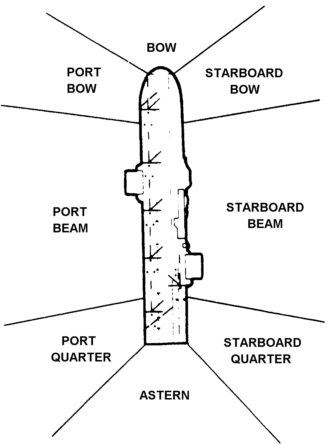
Figure 5-9. VFR relative position reporting
(d) The ship's land/launch frequency will be used for instructions and landing control. Strict radio discipline will be observed.
(e) Giving consideration to low-fuel-state aircraft, PriFly normally will give a "Charlie" to the number of aircraft for which there are available spots. Together with "Charlie," PriFly also will broadcast the BRC in degrees magnetic, altimeter, and wind condition across the deck. The pilot should plan the descent and break up to the landing pattern as shown in Figures 5-1, 5-2, and 5-3. Care should be taken to orient the landing pattern on the recovery course specified when it differs from the ship's heading. All pilots should take proper intervals at the upwind break.
(f) When a "Charlie number," such as Charlie 5, is given, the aircraft enters the landing pattern with the lead aircraft planning to be over the deck at the expiration of the number of minutes specified. A "Charlie" is given with the assumption that the first aircraft will be cleared to land upon arrival. When the "Charlie" spot number is given, the aircraft is clear to land. The pilot will indicate that the gear is down, if required, and give his seat position, as appropriate.
(g) LSEs will pick up landing helicopters at the 45-degree position in the approach turn of the Charlie pattern or at 100 yards astern in the helicopter night Case I recovery pattern.
NOTE: Wave-off and hold signals given by the LSE are mandatory; all other signals given by the LSE are advisory. Loss of visual contact with the LSE on final approach requires a wave-off.
(3) Landings. When aircraft are being recovered during VMC, the leader of the flight should plan to be on the deck with a minimum safe interval after the preceding aircraft has landed. When clearing aircraft to land, PriFly transmits relative direction, BRC, altimeter, and landing spots.
(4) Standard landing patterns.
(a) The Charlie pattern is the standard Case I daytime helicopter landing pattern. The landing pattern for port spots is an approach that starts not later than when the aircraft is abeam the intended point of landing. A turn is then made to intercept the 45-degree line at the 90-degree position and flight continued straight into the spot. Helicopters should not be landed on spots directly in front of other helicopters.
|
WARNING When helicopters approach on a 45-degree bearing to land directly in front of a spot occupied by another helicopter, rotor clearances (main and tail) between the two aircraft during the final portion of the 45-degree approach are significantly reduced. |
(b) When approaching a spot directly in front of a spot occupied by another helicopter, the pilot should terminate the final portion of the approach on the 45-degree bearing at a point abeam the intended landing spot. From this point, the pilot flies the final transition by sliding sideways to a hover over the landing spot. The pilot in the right seat should land the aircraft.
(c) The Charlie pattern and the helicopter night Case I recovery pattern are the standard Case I night helicopter landing patterns. The air officer will ensure that all airborne aircraft and the squadron duty officer are informed when changing from one night landing pattern to another. Simultaneous use of the Charlie pattern and the night Case I recovery pattern is not authorized.
(d) Completion of the helicopter night Case I recovery pattern depends on the locations of aircraft on the landing spots. If the landing spots aft of the assigned landing spot are clear, the helicopter may complete a straight-in approach over the stern and air-taxi to the landing spot. If obstructions are between the stern and the landing spot, the air officer will direct the pilot to adjust his pattern to fly close aboard the port side and intercept the 45-degree lineup of the assigned landing spot.
(5) Nonstandard helicopter landing patterns.
(a) Cross-deck. A cross-deck approach will be flown the same as the standard landing pattern except that the approach will continue across the flight deck to the assigned landing spot (Figure 5-3).
(b) Helicopter around stern. Starboard spots may be used by entering the normal Charlie pattern, calling abeam port quarters, and descending to 200 feet by the astern position. Continue up the starboard side to intercept an approximate 45-degree angle to the spot, and fly straight in (Figure 5-3).
(c) Helicopter modified straight-in. Depending on the amount of traffic in the pattern, PriFly may approve a straight-in approach to the spot.
NOTE: When directed, begin a straight-in approach far enough astern for the aircraft to be established positively on glide slope, at the proper airspeed, at a minimum distance of 1.5 miles, and at an altitude of 400 feet.
(6) Wave-off. Aircraft will be waived off --
On voice command from PriFly or loss of communications with PriFly or the LSO.
On command from the LSE or LSO.
Any time the pilot feels that the approach cannot be completed safely.
If visual contact with the LSE is lost on final approach (helicopters only).
The pilot will call "(aircraft identification) waving off" when the aircraft is parallel the BRC on the appropriate side of the ship and reenter the appropriate VMC recovery. Should reentry into the VMC pattern not be possible, the pilot will climb out straight ahead and request instructions from PriFly.
a. In-Flight Procedures. Before the aircraft enter the ship's control zone, pilots will complete the following actions:
(1) Determine if all ordnance has been expended after the firing mission has been completed. Make a visual check between aircraft of all rocket pods.
(2) Every effort will be made to fire or jettison hung ordnance, as appropriate. If the hung ordnance cannot be fired or jettisoned, the pilot should consider diverting to a land base.
(3) Notify the ship as soon as possible if the ordnance must be brought back to the ship. Do not bring hung ordnance into the ship's control zone without clearance from the AOCC/HDC or the tower. Include in the initial notification the amount and type of hung ordnance.
(4) Properly safe all weapon systems.
b. Shipboard Procedures. Before the aircraft lands, the following actions will be completed:
The bridge and other appropriate stations will be notified.
The appropriate HERO condition will be set.
Dearming crews will be standing by on station.
Approval from the ship's CO will be obtained before ordnance is jettisoned from the ship.
c. Air Officer Procedures. Before the aircraft lands, the air officer must complete the following actions:
Clear a landing spot for recovery.
Before the aircraft is recovered, announce on the 5 MC: "Stand by to recover (state type of aircraft) with hung ordnance on spot. Hung ordnance is (state amount and type). All personnel remain well clear of the flight deck area."
Ensure that the ordnance safety supervisor and the squadron dearming team are on station before recovery.
Ensure that all aircraft on the flight deck and in the landing pattern have secured HF and/or FM transmitters, IFF, TACAN, and radar altimeters, as required.
|
WARNING All flight deck personnel, including LSEs, will remain clear of the line of fire and/or danger area of an aircraft landing with hung ordnance. Only the minimum required personnel will remain near the landing area. The pilot will not leave the cockpit until all ordnance and weapon systems have been safed properly. |
5-6. HELICOPTER RECOVERY TIE-DOWN PROCEDURES
With the aircraft commander's concurrence and when the LSE gives the signal, chocks and tie-downs will be applied after the aircraft lands. They will remain attached until the aircraft is ready to be launched. During short on-deck times, such as when troops and supplies are being rapidly loaded, the aircraft may be chocked only. Tie-downs will be installed according to the individual aircraft operator's manuals. Unless otherwise specified, tie-downs will be attached to mooring rings in the vicinity of the main landing gear first.
|
WARNING Any maneuvering of the ship while rotors of aircraft on the deck are turning will be done so that the winds and deck motion are kept within the operating envelopes of the aircraft. The pilot of an aircraft on deck with rotors turning will be informed of an impending ship's turn. |
a. Personnel Debarkation.
(1) Pilots of ramp-equipped helicopters will not lower the ramps to discharge passengers until the LSE gives the signal.
(2) When troops are off-loading, the LSE will not signal for the ramp until the CCO troop handlers are present and recoveries or launches are complete on adjacent spots. The CCO handlers will escort the troops from the flight deck to the troop shelters as directed by the CCO. Flight deck, flight crew, or CCO personnel will escort passengers to a safe area.
b. Rotor Disengagement.
(1) Before rotors are disengaged and/or the engines shut down, the LSE will ensure that the signal to disengage is received from the flight deck officer who in turn receives the signal from the air officer. The LSE will ensure that the wheels are chocked, rotors are clear of personnel, and tie-downs are installed properly.
NOTE: Landing gear, external auxiliary fuel tank, and ordnance safety pins will be inserted before rotors are disengaged and/or engines shut down.
(2) Rotor blades should not be disengaged while the ship is in a turn unless authorized by the ship's CO or his designated representative. The aircraft commander will be advised of the anticipated wind parameters and the ship's heel before a turn is executed.
(3) The pilot will not disengage the rotors until he receives the signal from the LSE.
(4) The air officer will ensure that the proper wind conditions exist, according to the applicable NATOPS manuals, for disengaging rotor blades.
(5) If high winds exist, rotors will be disengaged starting with the forward most aircraft and working aft.
|
WARNING Reported winds as displayed in PriFly may vary greatly with existing winds over the deck. Extreme care should be exercised when engaging or disengaging rotors if other aircraft are launching or recovering. Rotor engagement will not be attempted unless the tie-down configuration is as stated in the aircraft NATOPS flight manual. Failure to comply with this requirement may induce ground resonance. |
Night operations are among the most critical for both pilots and flight deck crews. The tempo of operations will be reduced compared to day operations. To enhance safety, the pilots and flight crew must handle the aircraft slowly and carefully. All concerned personnel will be indoctrinated in night operations procedures.
a. Postflight Maintenance Inspections. Postflight inspections will be performed the same way they are for day operations. However, a red-lens flashlight will be used.
|
WARNING Maintenance on or postflight of any portion of an aircraft that extends over the edge of the deck of the ship is prohibited. |
b. Flight Deck Operations. Flight deck operations at night may cause some confusion between pilots and crews and the directors. All personnel must clearly understand the signals. During night operations--
The LSE will be equipped with amber wands.
All flight deck personnel will use clear lens goggles.
All optical landing aids and flight deck lighting will be checked for proper operation before recovery operations begin.
Lighting is critical. Under amber or red flight deck lighting conditions, white lens flashlights will not be used.
c. Wind Limitations. Wind limitations shown in the aircraft operator's manual or the shipboard operating bulletin will be complied with for all night recoveries. Commanding officers may establish more restrictive limitations. Flight leaders or aircraft commanders will be provided the ship's BRC as early as possible so the flight can maneuver properly to enter the designated pattern.
d. Helicopter Night Recovery. Recovery procedures will be the same as for day operations except external lights will be used for signaling (see Figure 4-7).
e. Helicopter Optical Landing Aids.
(1) The SGSI is a helicopter optical landing aid. It allows a pilot to visually establish and maintain the proper glide slope for a safe approach (Figure 5-10). The visual acquisition range is approximately 3 nautical miles at night under favorable environmental conditions. The light is projected through a horizontal arc 40 degrees wide. It provides a single vertical arc of green light (1.5 degrees), amber light (1 degree), and red light (6.5 degrees). The color of the light tells the pilot if he is above (green), below (red), or on (amber) the proper glide slope. By adjusting the aircraft's altitude to keep the amber beam visible, the pilot can maintain a safe 3-degree glidepath to the transition zone. Aircraft executing an SGSI approach normally will intercept the glide slope at the 180-degree position at 300 feet altitude and one-half mile abeam the intended point of landing. The SGSI normally is used from initial acquisition to about the 45-degree position where a visual transition is made to flight deck cues.
(2) Before starting a night TACAN straight-in approach, the SGSI should be set at 180 degrees azimuth relative to the ship. Helicopters executing straight-in approaches normally should intercept the SGSI glide slope at approximately 1,180 feet at a three-nautical-mile run. In addition to other radar approach voice reports, the pilot will report glide slope acquisition to AOCC, HDC, or PriFly, as appropriate.
NOTE: The glide angle indicator light uses the same beam colors as the SGSI. However, with the glide angle indicator light, the amber beam means that the pilot is above the glidepath, the green beam on the glidepath, and the red beam below the glidepath.
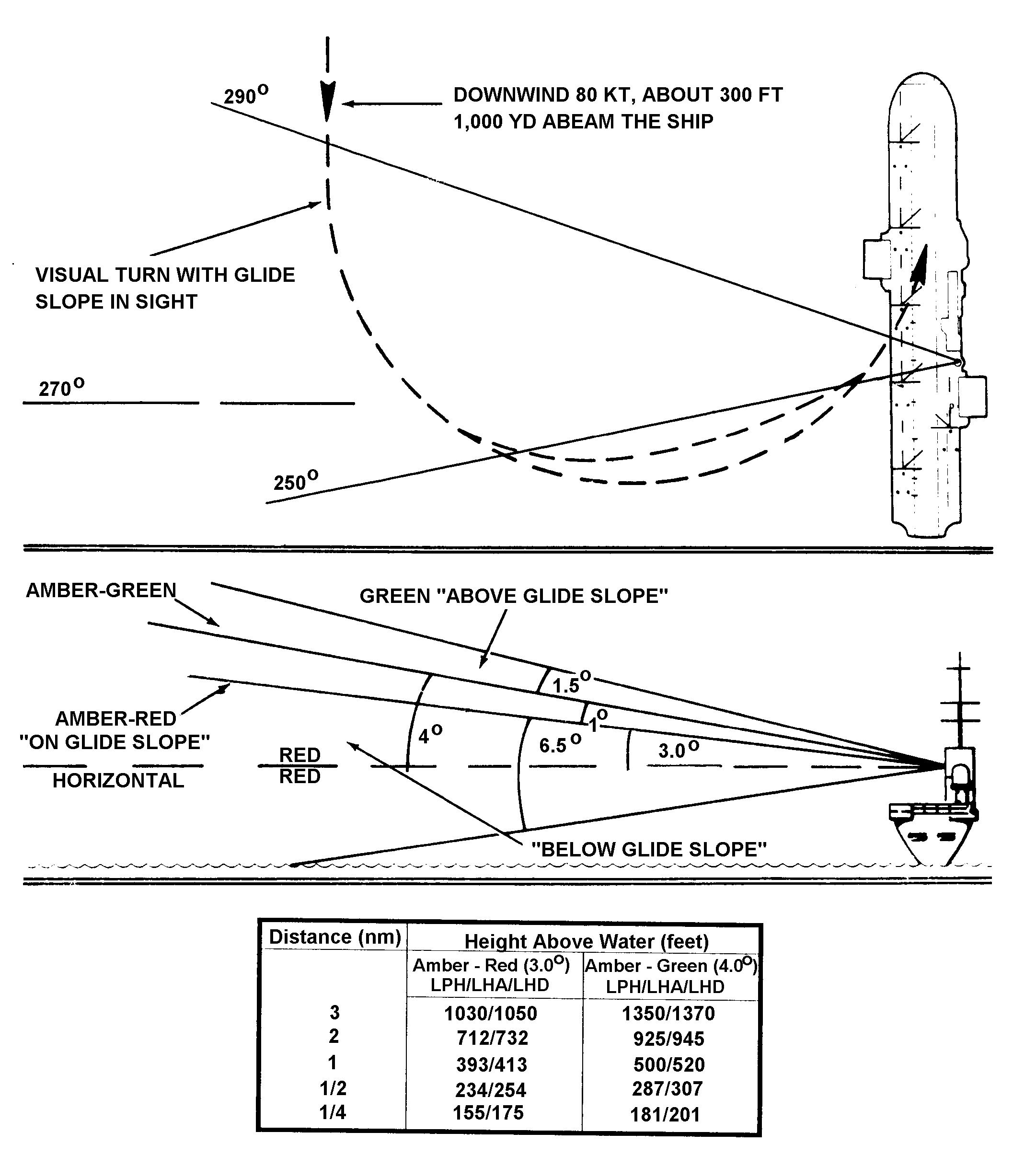
Figure 5-10. Forward stabilized glide slope indicator
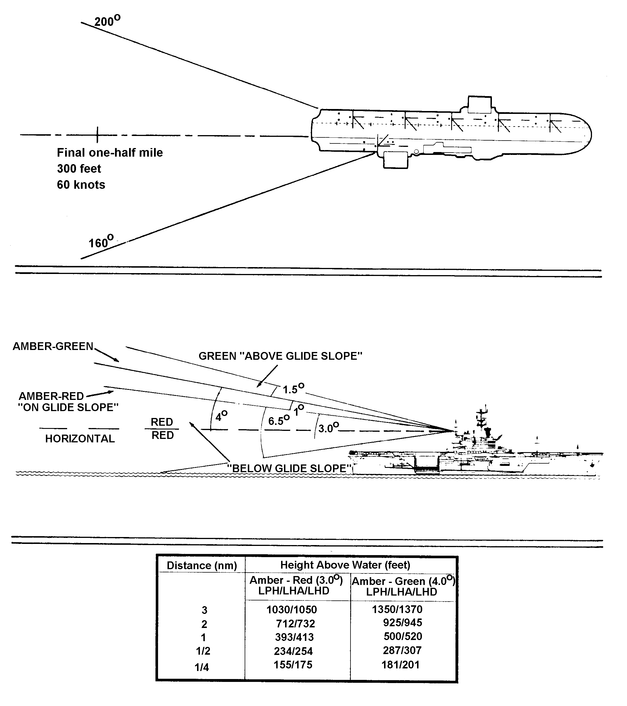
Figure 5-10. Forward stabilized glide slope indicator (continued)
(3) A red wave-off light is installed on each side of the SGSI which is located forward on the island. The wave-off and cut lights of the CAI Mod 2 complement the SGSI located on the aft end of the island.
5-8. SPECIAL SAFETY PRECAUTIONS
The following items deserve special attention during aircraft operations:
a.
b. Personnel will not stand in or in any way block the entrances to the island structure or exits off the catwalks.
c. Personnel will not sleep or lounge on the flight deck, catwalks, galleries, or gun tubs during flight quarters.
d. Personnel will stay clear of all cargo elevator hatches and weapons mounts outlined by danger lines.
e. Personnel will not turn their backs to landing aircraft.
f. Except in an attempt to avert an accident, no director will give signals to a pilot who is being controlled by another director.
g. To reduce the possibility of an aircraft landing on a foul deck, landing spot and deck edge lights will not be turned on without the air officer's permission.
h. During instrument recoveries, PriFly will keep AOCC/HDC advised of the status of the deck and provide the estimated time the deck will be clear. AOCC/HDC will keep PriFly advised of the position of the nearest aircraft.
i. CIC and AOCC/HDC will keep PriFly informed of any aircraft known or suspected to have radio failure.
j. During night operations, green and red wands will be used only by the flight deck supervisor or launch officer.
k. Taking flash pictures during flight operations is prohibited.
l. Recovery will not be planned to any spot where aircraft or other obstacles would come within 10 feet of the rotor plane.
m. Left seat landings immediately behind a helicopter with the tail rotor turning are not authorized.
n. Night approaches to spot 1 are not authorized.
o. Left seat landings on spot 2 (LHA and LPH) are not recommended.
p. Right seat landings on spot 1 (LPH) and spot 3 (LHA) are not recommended.
5-9. EMISSION CONTROL, ZIP-LIP, AND LOST COMMUNICATION PROCEDURES
When radio communications are limited, operations may be conducted using other means of communication. Visual communications become extremely important, including the proper use of the ship's aircraft lighting, flag command, and display signals. The Aldis lamp, blinker, and hand and arm signals are necessary in conducting safe flight operations. These signals are explained in Appendixes A and B. Both the aircraft and the controlling ships will monitor the land/launch frequency. Radio transmissions will not be authorized unless required for safety of flight. All flight operations conducted under EMCON conditions will be briefed thoroughly and coordinated between the squadron and the ship's control-line agencies. During EMCON conditions, all personnel have an increased responsibility to conform to safe operating procedures.
a. EMCON Recovery Procedures.
(1) The ceiling will be 500 feet above the highest normally prescribed Delta pattern with a minimum of 3 nautical miles visibility and a well-defined horizon. Returning pilots will plan to be in the Delta pattern before the scheduled recovery time. They will shift to and monitor the PriFly frequency when the ship is in sight. Each aircraft will have its anticollision lights on. Position lights will be on steady bright when the aircraft is within 10 nautical miles of the ship.
(2) Once established in the Delta pattern, the position lights will be set to flashing. The pilot will receive a flashing green Aldis lamp signal at the abeam position in the Delta pattern. The pilot will acknowledge by turning the navigation lights to steady-bright, leaving the anticollision light on, and descending to the Charlie pattern. At the abeam position, the pilot will receive a steady green Aldis lamp signal, conform to normal lighting procedures, and continue with the approach.
b. Zip-Lip Procedures. During zip-lip operations, recovery procedures will be the same as during EMCON. Unless radio communications are required for safety of flight, the appropriate hand, flag, and light signals will be used..
|
NEWSLETTER
|
| Join the GlobalSecurity.org mailing list |
|
|
|

