APPENDIX G
HELICOPTER/SHIP INTERFACE
This appendix shows the compatibility between Army helicopters and Navy and Coast Guard ships.
Section I. USN/USCG Ship and Army Helicopter Compatibility
G-1. SHIP/HELICOPTER OPERATIONS
The data shown in the tables and figures in this appendix are extracted from NWP 3-04.1M and are provided for information only. If differences exist between NWP 3-04.1M and the information in this manual, NWP 3-04.1M takes precedence.
a. Explanation of Tables. Table G-1 (page G-3) gives the definition of the acronyms referred to in Tables G-2 (page G-4) and G-3 (page G-6). Tables G-2 and G-3 show ship and helicopter combinations suitable for takeoff, landing, and vertical replenishment.
(1) Helicopter rotor diameter, fuselage configurations, landing gear arrangement, maximum gross weight, ship structures, and flight deck obstructions were considered to obtain the data in these tables. The tables show combinations of ships and aircraft that are suitable for safe operations during clear weather conditions without servicing facilities.
(2) The combinations do not constitute authority to operate nor do they imply certification of various facilities for the helicopters noted. Ships are listed based on their designed facilities. Certification of each individual facility must be verified before actual operations at that facility. Preferably, this will be done during the presail conference.
b. Table Annotations.
(1) In all cases, the operating helicopter is restricted to landing with the fuselage parallel to the landing lineup line and the forward landing gear or skid support within the touchdown circle inner edge.
(2) In Table G-2 under the column, "VERTREP TYPE," Type 1, Type 2, and Special Type 2 operations are defined as follows:
(a) Type 1 operations. The helicopter must hover with all rotor hubs above the segmented lineup line.
(b) Type 2 operations. The helicopter must hover with all rotor hubs above or aft of the "T" lineup line.
(c) Special type 2 operations. In general, pilots of helicopters that have a rotor diameter of less than 55 feet must follow the guidance for VERTREP Type 2 operations. Helicopters that have a rotor diameter of more than 55 feet must be hovered with all rotor hubs above or aft of the "T-ball" lineup lines.
(3) In Table G-2 under the column, "VERTREP HELICOPTER," Class 4 and Class 5 VERTREP operations are defined as follows:
(a) Class 4 VERTREP operations require that the helicopter be hovered at a minimum altitude in excess of 5 feet above the operating deck.
(b) Class 5 VERTREP operations require that the helicopter be hovered at a minimum altitude in excess of 15 feet above the operating deck.
(4) In Table G-3 under the column "OPERATING LEVEL," the letter "I" denotes a day/night IMC capability; the letters "II" denote a day/night VMC capability; and the letters "III" denote a day VMC capability.
(5) In Table G-3, the dual-circle, air-capable ship matrix addresses all helicopters that may be operated simultaneously on the same deck. Clearances for any particular helicopter landing at the aft circle are assured only when a parked helicopter or any other object remains forward of the safe park line.
|
WARNING Some Army helicopters have not been tested in the electromagnetic environment of all classes of ships. When operations are being conducted with Navy ships, consideration must be given to potential radiation hazards, electromagnetic interference, and electronic vulnerability effects. |
G-2. SHIP DESIGNATIONS
a. Definition of Acronyms. Table G-1 lists the definitions of ship acronyms that are referred to in Tables G-2 and G-3.
Table G-1. Acronym definitions
|
b. Explanation of Suffixes and Prefixes.
(1) The suffix "N" denotes a nuclear powered vessel.
(2) The prefix "T" refers to a tactical ship. On a tactical ship, the crew consists of military sailors. A nontactical ship is one that belongs to the Military Sealift Command. These ships have civilian crews and a military captain.
c. Listing of Ships. All ships are not individually listed in Tables G-2 and G-3. Rather, they are listed by class. For example, DDG 993 (USS Kidd) represents four ships: DDGs 993, 994, 995, and 996. To find a specific ship, refer to NAEC-ENG-7576, the Navy's catalog of aviation-capable ships. Once the specific ship is identified in the resume manual, its specific capabilities can be found in this appendix.
Table G-2. Single-circle air-capable ships
|
LANDING HELICOPTER |
VERTREP HELICOPTER |
||||||||||
|
SHIP |
AREA |
SS OR CLASS |
LEVEL/ CLASS |
UH-1 |
OH-6 |
OH-58D |
UH-60 |
CH-47 |
VERTREP TYPE |
CH-47 |
UH-60 |
|
AD 38 |
AFT |
S |
II, 2A |
X |
X |
X |
SP2 |
4 |
4 |
||
|
AD 41 |
AFT |
C |
II, 2A |
X |
X |
X |
X |
SP2 |
4 |
4 |
|
|
AE 27 |
AFT |
C |
I, 2A |
X |
X |
X |
X |
SP2 |
4 |
4 |
|
|
AGF 3 |
AFT |
S |
I, 2A |
X |
X |
X |
X |
SP2 |
4 |
4 |
|
|
AO 177 |
AFT |
C |
II, 3 |
X |
X |
X |
SP2 |
4 |
4 |
||
|
AOE 1 |
AFT |
C |
I, 2A |
X |
X |
X |
X |
SP2 |
4 |
4 |
|
|
AOE 6 |
AFT |
C |
I, 2A |
X |
X |
X |
X |
SP2 |
4 |
4 |
|
|
AOR 6 |
AFT |
S |
I, 2A |
X |
X |
X |
X |
SP2 |
4 |
4 |
|
|
CG 47 |
AFT |
C |
I, 2A |
X |
X |
X |
2 |
4 |
4 |
||
|
MAIN |
I, 5 |
1 |
5 |
5 |
|||||||
|
FWD |
III, 4 |
1 |
4 |
4 |
|||||||
|
CGN 36 |
AFT |
C |
I, 4 |
X |
X |
X |
2 |
4 |
4 |
||
|
FWD |
III, 4 |
1 |
4 |
4 |
|||||||
|
DD 963 |
AFT |
C |
I, 2A |
X |
X |
X |
2 |
4 |
4 |
||
|
MAIN |
I, 4 |
1 |
4 |
4 |
|||||||
|
FWD |
III, 4 |
1 |
4 |
4 |
|||||||
|
DDG 51 |
AFT |
C |
I, 4 |
X |
X |
X |
2 |
4 |
4 |
||
|
FWD |
I, 4 |
1 |
4 |
4 |
|||||||
|
DDG 993 |
AFT |
C |
I, 2A |
X |
X |
X |
2 |
4 |
4 |
||
|
MAIN |
I, 4 |
1 |
4 |
4 |
|||||||
|
FWD |
III, 4 |
1 |
4 |
4 |
|||||||
|
FFG 7 |
AFT |
C |
I, 2A |
X |
X |
SP2 |
4 |
4 |
|||
|
FWD |
III, 5 |
1 |
5 |
5 |
|||||||
|
IX 514 |
MAIN |
S |
II, 3 |
X |
X |
X |
X |
2 |
4 |
4 |
|
|
LCC 19 |
AFT |
C |
I, 2A |
X |
X |
X |
X |
X |
2 |
4 |
4 |
|
LSD 36 |
AFT |
C |
II, 2A |
X |
X |
X |
X |
2 |
4 |
4 |
|
|
T-AE 26 |
AFT |
S |
I, 2A |
X |
X |
X |
X |
SP2 |
4 |
4 |
|
|
T-AFS 1 |
AFT |
C |
I, 2A |
X |
X |
X |
X |
SP2 |
4 |
4 |
|
|
T-AFS 8 |
AFT |
C |
I, 2A |
X |
X |
X |
SP2 |
4 |
4 |
||
|
T-AH 19 |
MAIN |
C |
I, 2A |
X |
X |
X |
X |
X |
3 |
4 |
4 |
|
T-AK 3000 |
AFT |
C |
II, 3 |
X |
X |
X |
X |
2 |
4 |
4 |
|
|
T-AK 3005 |
AFT |
C |
II, 3 |
X |
X |
X |
X |
1 |
4 |
4 |
|
|
T-AK 3008 |
AFT |
C |
II, 3 |
X |
X |
X |
1 |
4 |
4 |
||
|
T-AO 188 |
AFT |
C |
II, 3 |
X |
X |
X |
X |
2 |
4 |
4 |
|
|
WHEC 715 |
AFT |
C |
I, 2A |
X |
X |
X |
2 |
4/5 |
4/5 |
||
|
WMEC 901 |
AFT |
C |
I, 2A |
X |
X |
X |
X |
2 |
4 |
4 |
|
Table G-3. Dual-circle air-capable ships
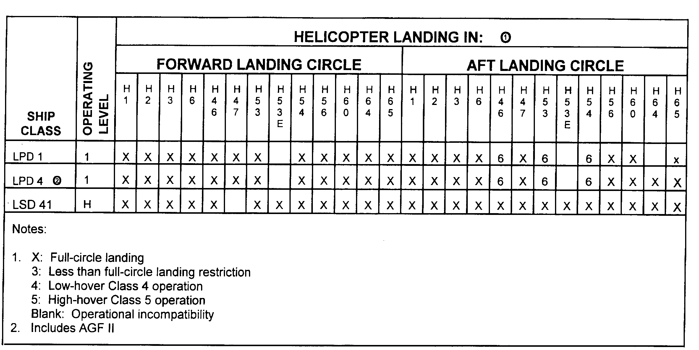
Table G-3. Dual-circle air-capable ships (continued)

Section II. Army Helicopter Wind Envelopes
G-3. AIRCRAFT WIND LIMITATIONS
a. The safe launch and recovery wind limitations are presented in NWP 3-04.1M and COMDTINST M3710.2-series. These publications can be obtained using the procedures outlined in Chapter 1.
(1) Figures G-1 (page G-10) and G-2 (page G-11) are to be used when specific flight limit envelopes are not available. Procedures should be agreed upon before starting the approach. The envelopes are for a normal approach to the spot and the helicopter aligned the with ship's centerline at touchdown. The two wind envelopes present wind-over-deck limitations relative to the ship and represent safe operating conditions as tested to date.
(2) Heavy lines on the envelopes denote where specific problems were encountered during testing such as approaching a flight control limit or excessive turbulence. Ship pitch and roll limitations are left to the judgment of the ship's commanding officer and embarked aviation unit commander except where listed on the appropriate envelopes.
|
WARNING Considerable differences may exist between the flight deck winds and those measured by bridge level anemometers. However, aircraft wind limitations contained in this appendix and shipboard operating bulletins are based on winds measured by the windward bridge-level anemometer. When operations are being conducted near the outer wind limits, the probability of damage increases sharply when wind gusts exceed 10 knots. Also, the maximum safe wind in conjunction with excessive ship pitch and/or roll can make flight operations unacceptably hazardous. Common sources of turbulence are stack gasses and wash, ship superstructures, deck protrusions, and rotor wash or jet blast caused by adjacent aircraft taking off and landing. |
b. The Naval Air Warfare Division, Patuxent River, Maryland, conducts dynamic interface testing of all helicopter and ship class combinations to develop all aspects of shipboard helicopter dynamic operational compatibility. DI testing investigates the effects of ship airwake, ship motion, and ship lighting and marking. It also investigates the effects of ship and helicopter operations. The Army Shipboard Testing Office at NAWCAD, DSN 342-1342 or 342-1336, conducts DI testing of Army aircraft.
(1) The significant result of DI testing is the development of operational launch and recovery, engage or disengage, and helicopter in-flight refueling envelopes. Each of these depicts the wind, speed, direction, and ship motion conditions conducive to producing consistently safe shipboard operations. DI certifications of each ship and helicopter combination are required before any shipboard flight operations are conducted that are beyond the bounds of the DI general envelope.
(2) Aircraft that have not undergone DI testing or that do not have a DI-certified envelope are restricted to the use of the general launch and recovery wind limitation charts for the appropriate class ship. Comments or questions about the wind envelopes should be addressed to:
Commander
Naval Air Systems Command
(Code PMA 251, Aircraft Launch and Recovery Equipment)
1421 Jefferson Davis Highway
Arlington, VA 22243-5120
Telephone: DSN 664-3355
Commercial, (703) 604-3355
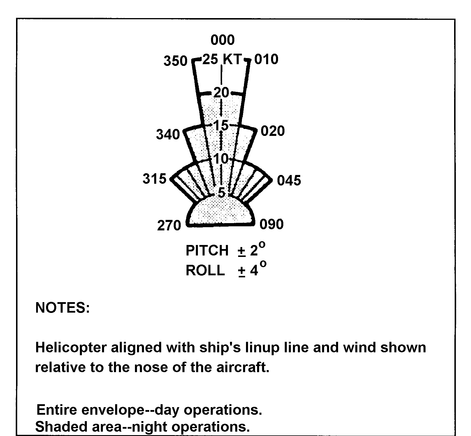
Figure G-1. General launch and recovery wind limits
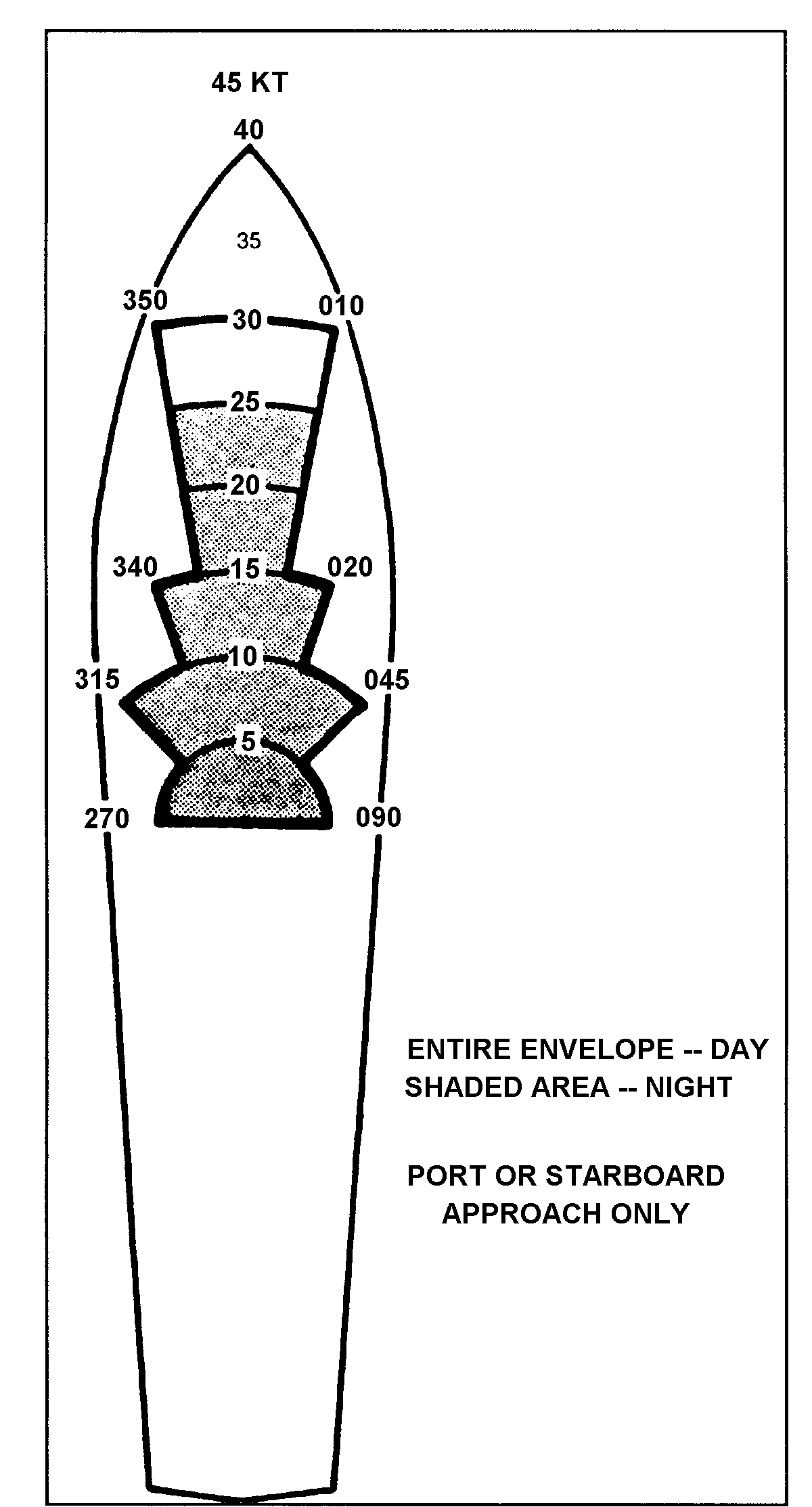
Figure G-2. General launch and recovery wind limits for LHA and LPH class ships
Section III. Typical Layouts, US Navy and USCG Ships
Figures G-3 through G-22 represent typical layouts of Navy and USCG ships as shown in NAEC-ENG-7576. These figures are for information purposly. The facilities resume must be consulted for the most current information on an assigned ship.
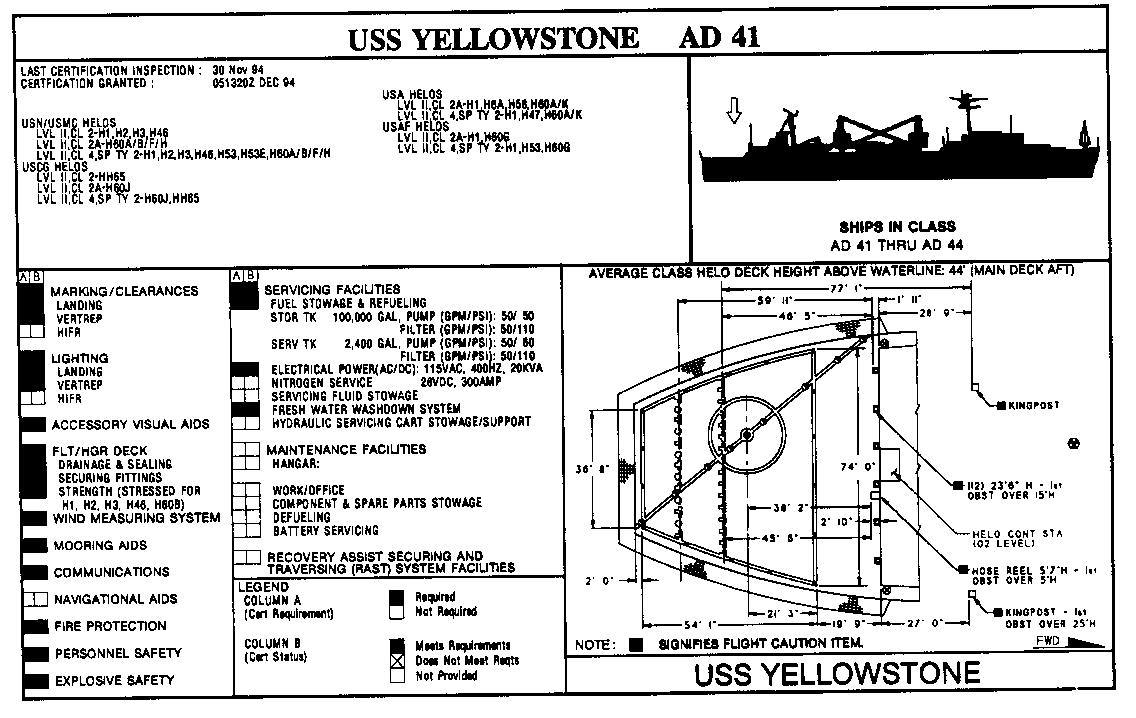
Figure G-3. Layout of the USS Yellowstone (AD 41)
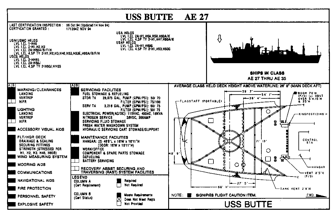
Figure G-4. Layout of the USS Butte (AE 27)
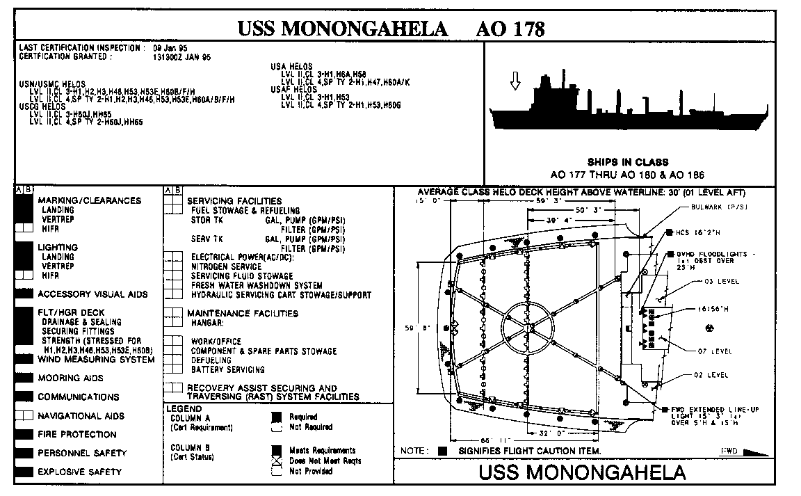
Figure G-5. Layout of the USS Monongahela (AO 178)
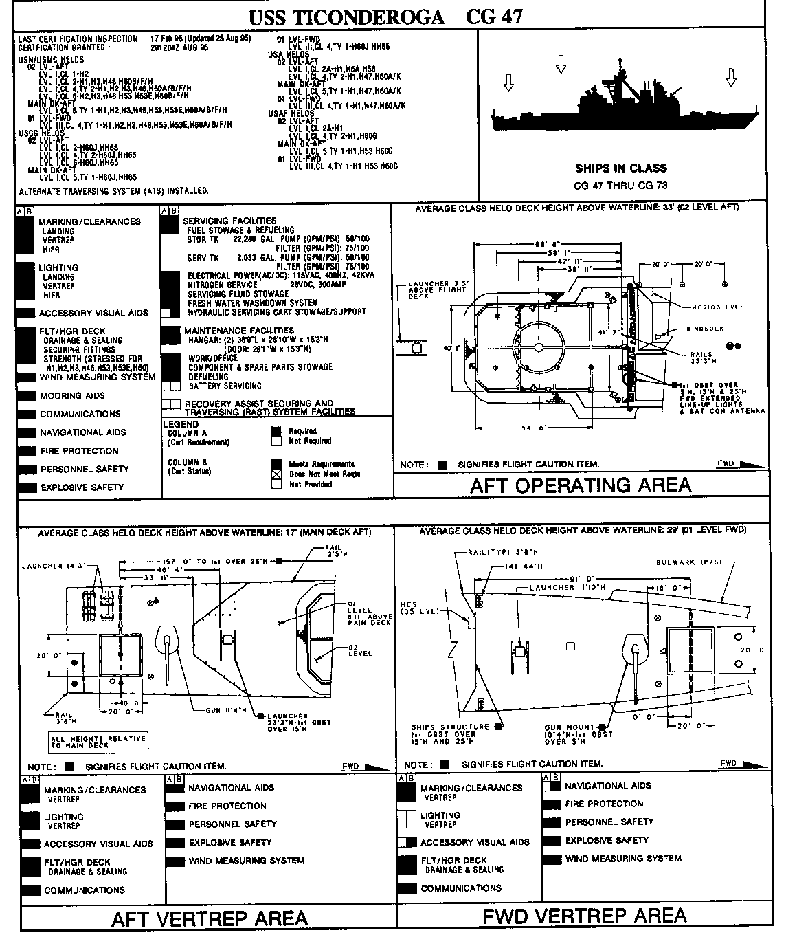
Figure G-6. Layout of the USS Ticonderoga (CG 47)
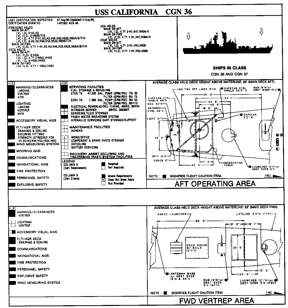
Figure G-7. Layout of the USS California (CGN 36)
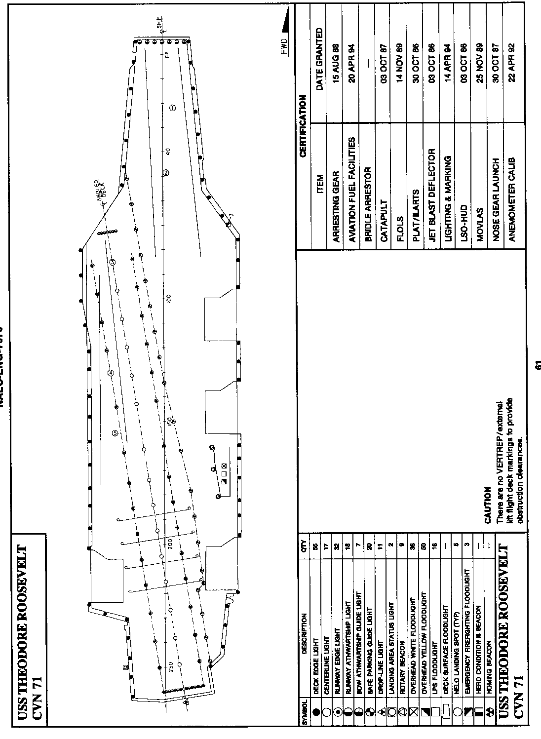
Figure G-8. Layout of the USS Theodore Roosevelt (CVN 71)
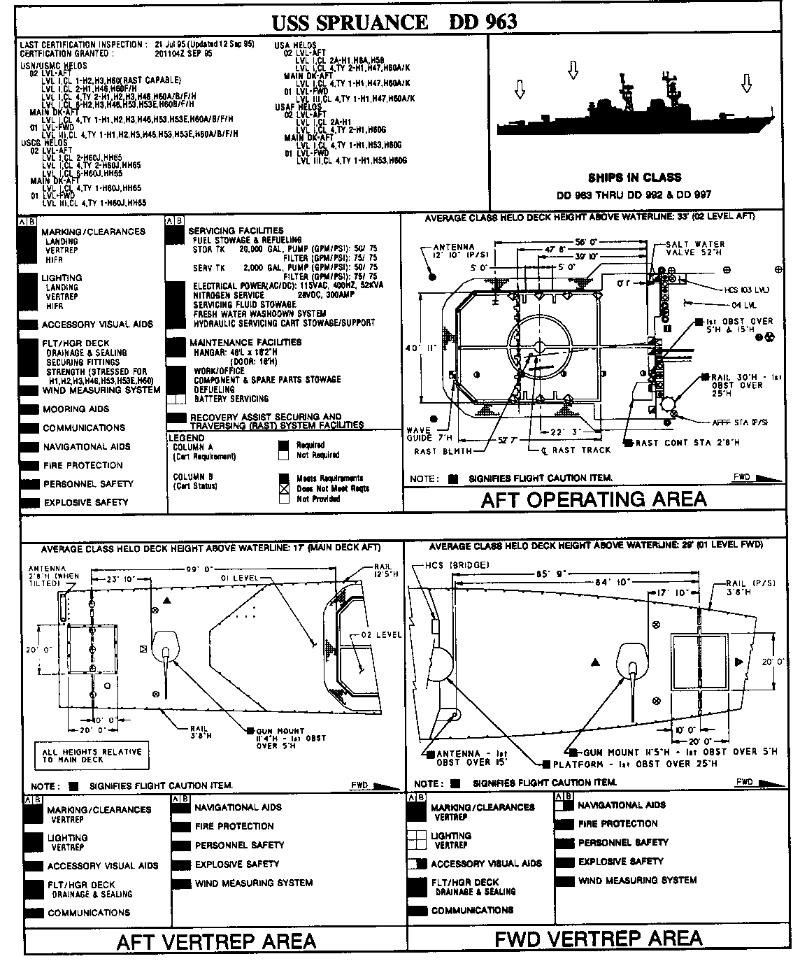
Figure G-9. Layout of the USS Spruance (DD 963)
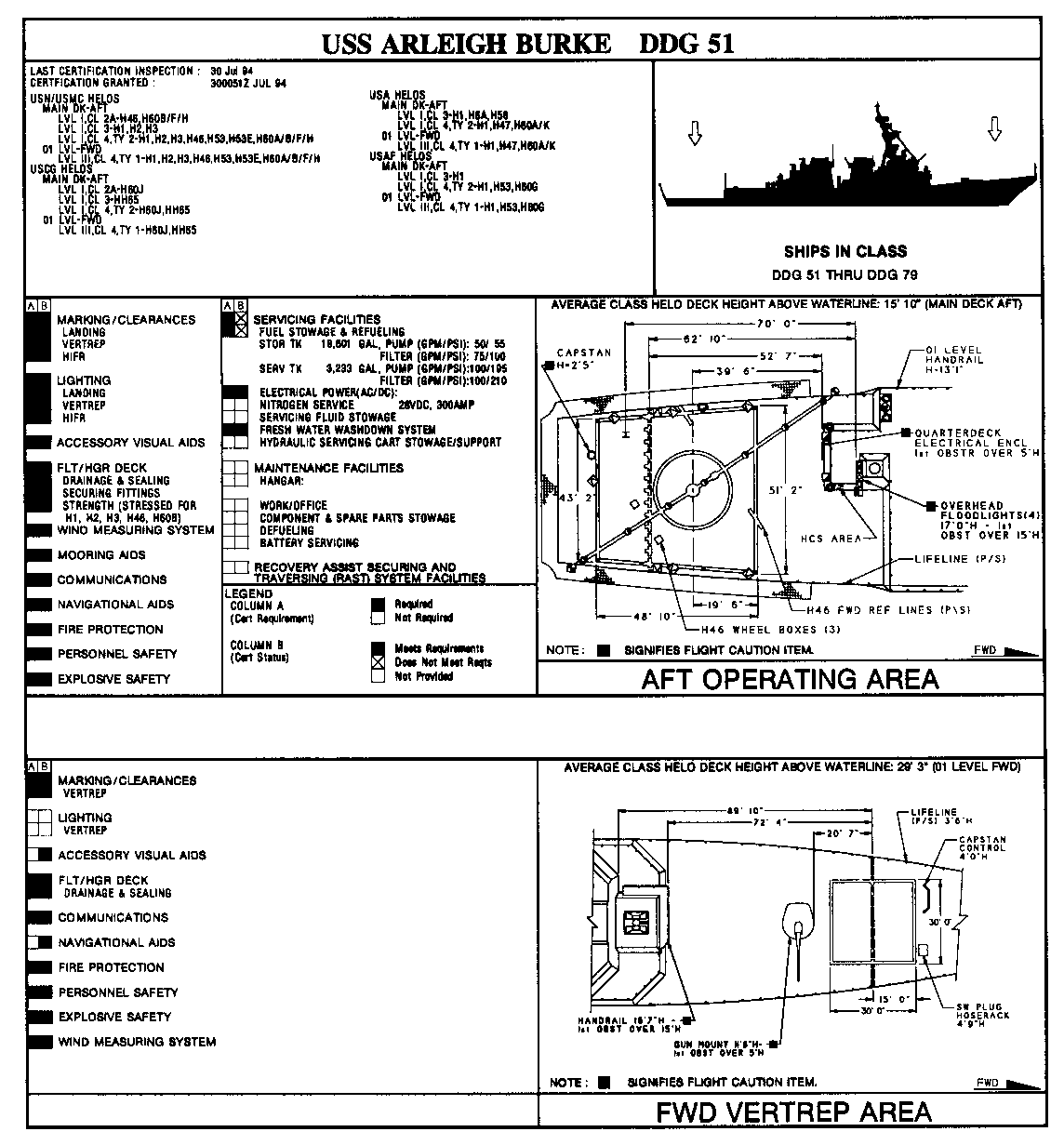
Figure G-10. Layout of the USS Arleigh Burke (DDG 51)

Figure G-11. Layout of the USS Kidd (DDG 993)

Figure G-12. Layout of the USS Oliver Hazard Perry (FFG 7)
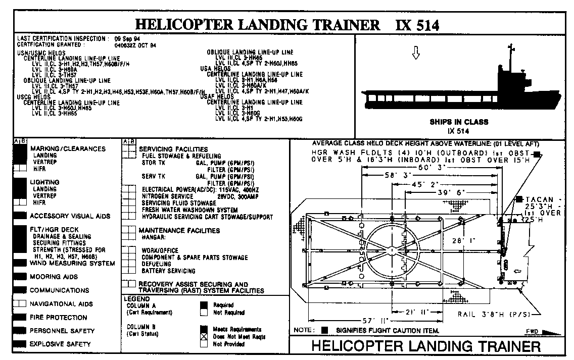
Figure G-13. Layout of the Helicopter Landing Trainer (IX 514)
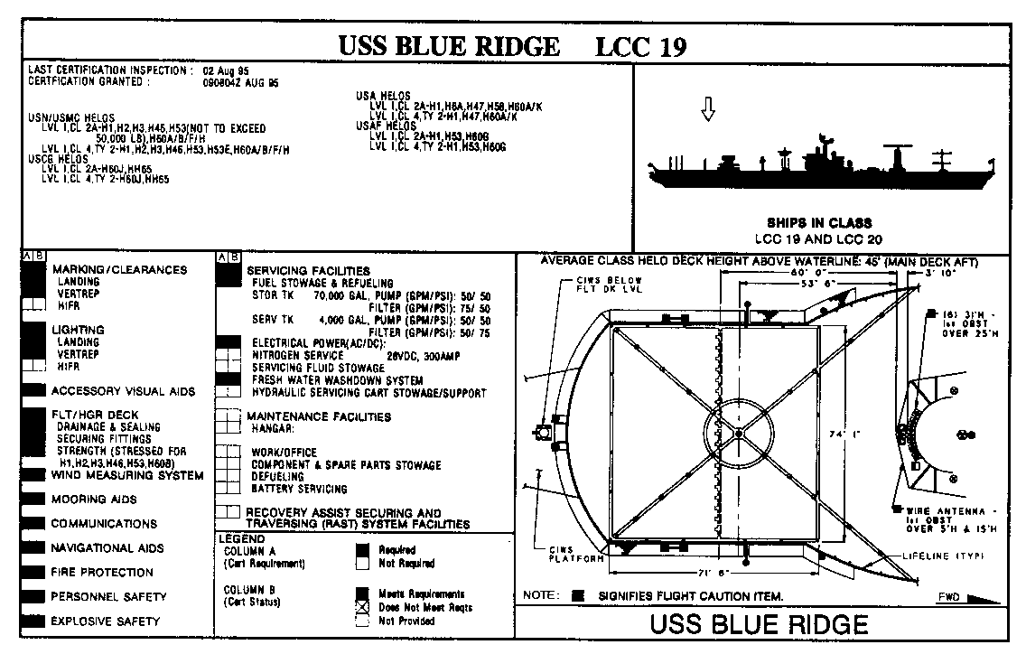
Figure G-14. Layout of the USS Blue Ridge (LCC 19)
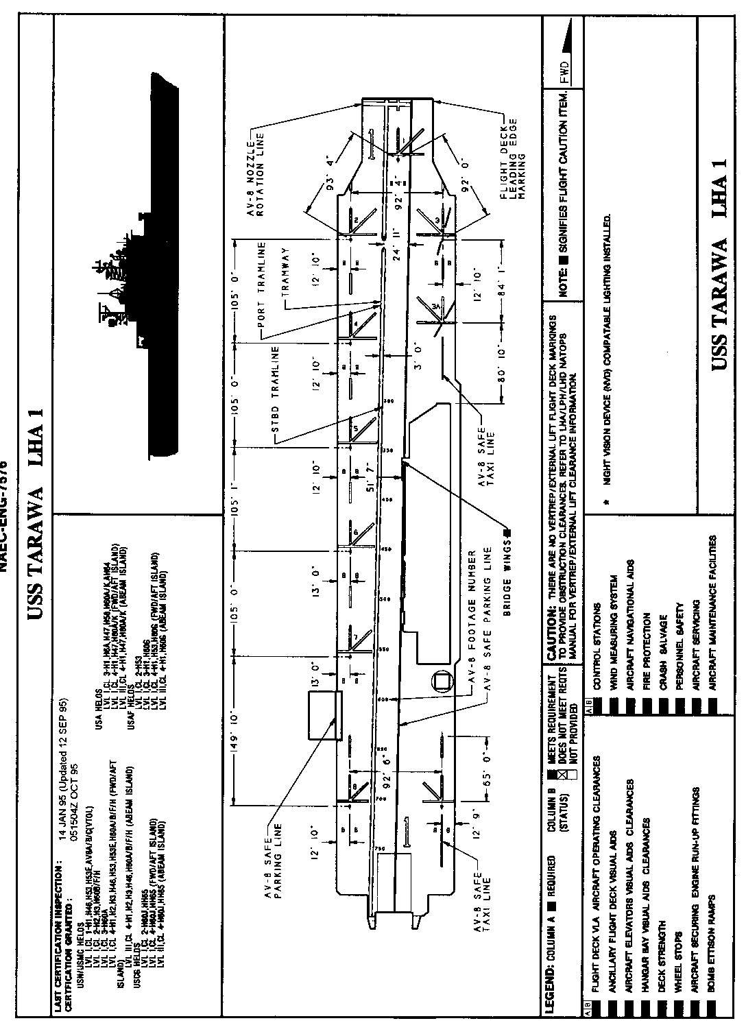
Figure G-15. Layout of the USS Tarawa (LHA 1)

Figure G-15. Layout of the USS Wasp (LHD 1)
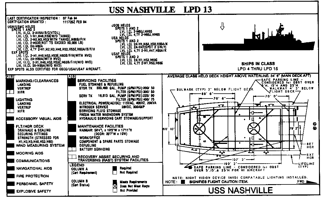
Figure G-17. Layout of the USS Nashville (LPD 13)
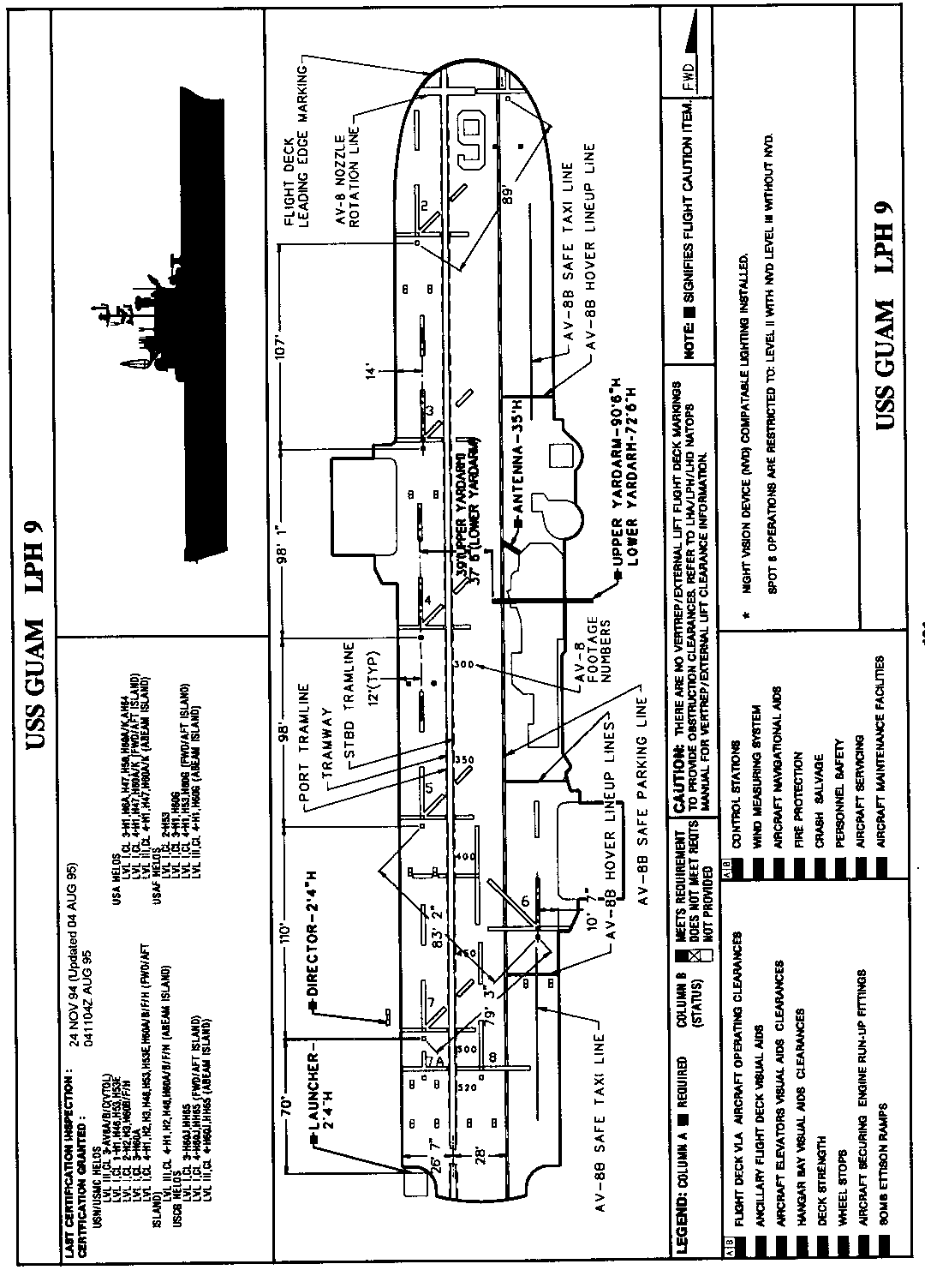
Figure G-18. Layout of the USS Guam (LPH 9)
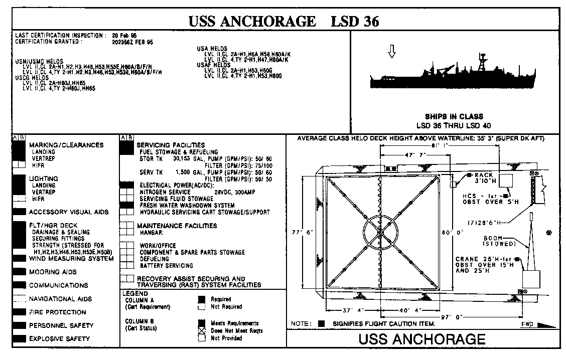
Figure G-19. Layout of the USS Anchorage (LSD 36)
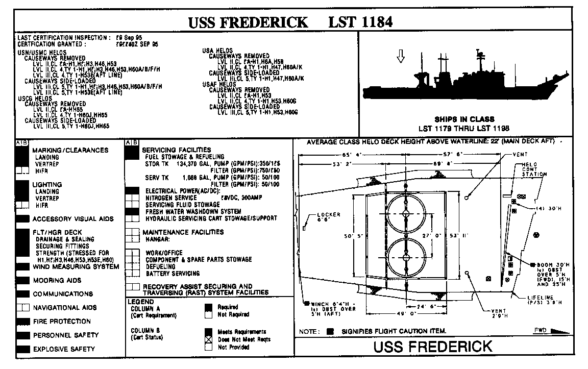
Figure G-20. Layout of the USS Frederick (LST 1184)
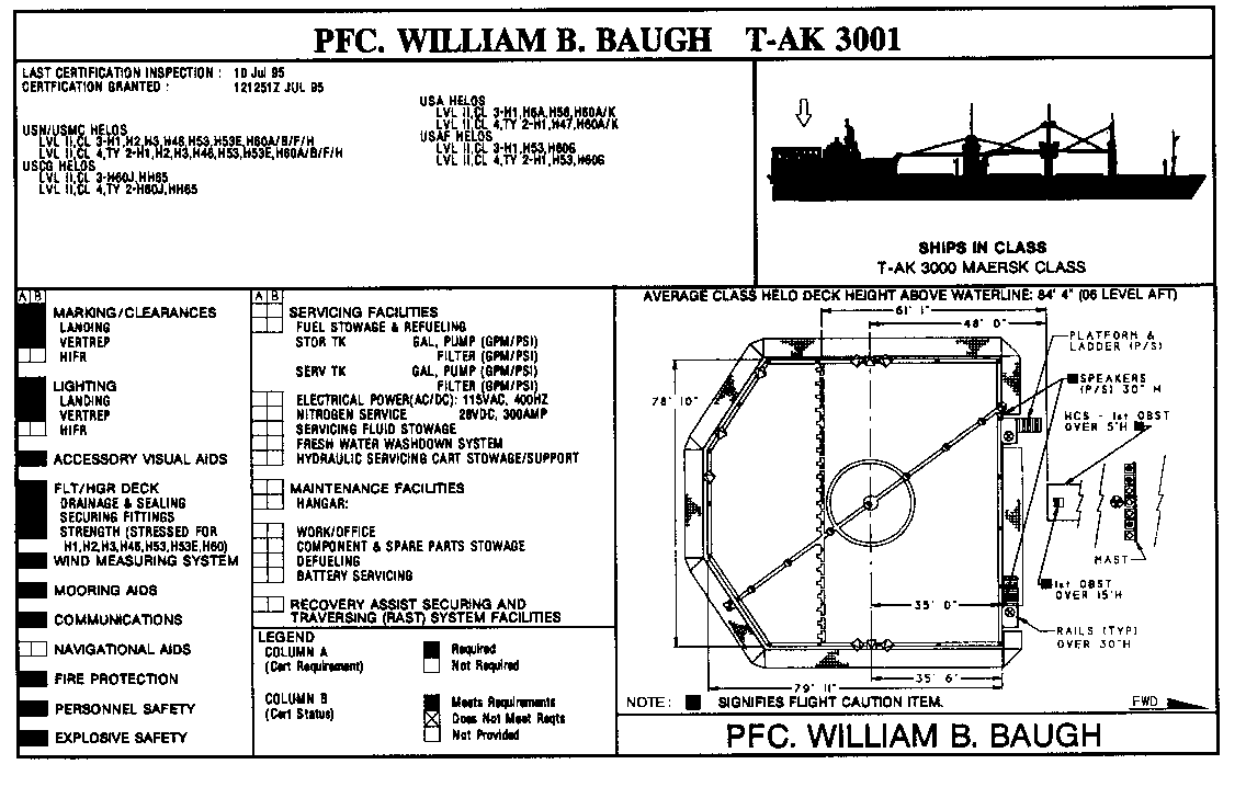
Figure G-21. Layout of the PFC. William B. Baugh (T-AK 3001)
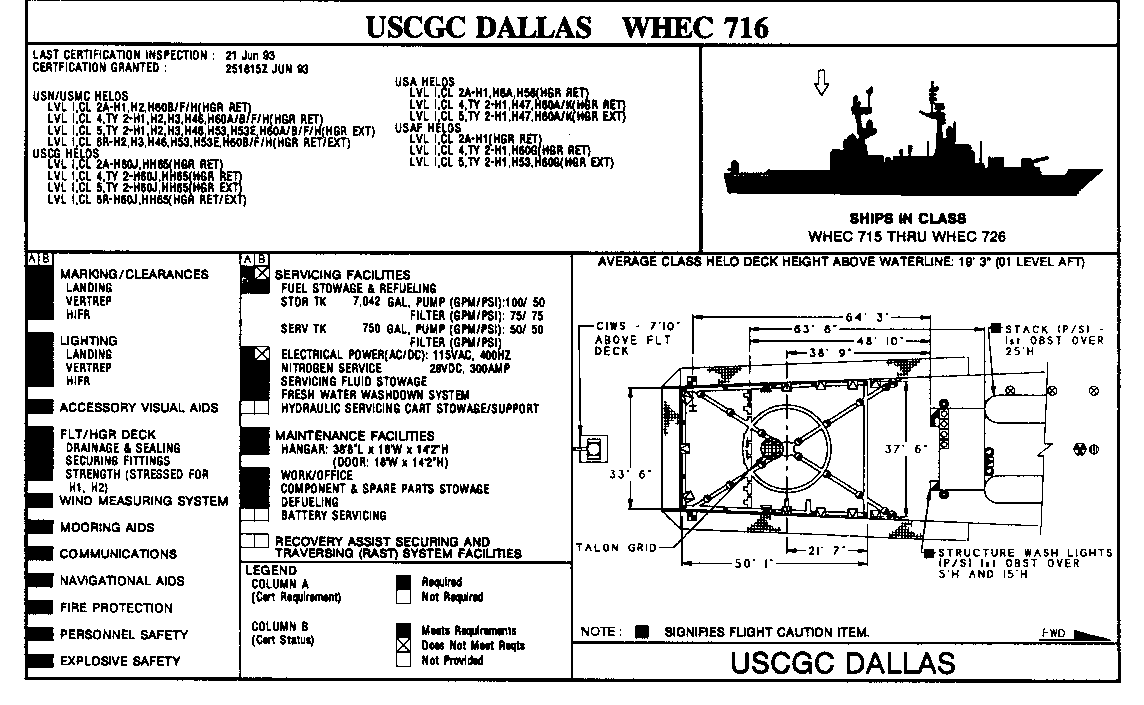
Figure G-22. Layout of the USCGC Dallas (WHEC 716)
|
NEWSLETTER
|
| Join the GlobalSecurity.org mailing list |
|
|
|

