|
RDL Homepage |
Table of Contents |
Document Information |
Download Instructions |
LESSON 1
ANTENNA PRINCIPLES AND CHARACTERISTICS
Critical Tasks: 01-5705.07-0003
01-5879.07-9001
OVERVIEW
LESSON DESCRIPTION:
In this lesson, you will learn about the theory of antennas, to include the principles of antenna radiation, the characteristics of antennas, and the formulas used in antenna design.
TERMINAL LEARNING OBJECTIVE
| ACTION: | Explain basic antenna theory. |
| CONDITION: | Given this lesson. |
| STANDARD: | To demonstrate competence, you must achieve a minimum of 70 percent on the subcourse examination. |
| REFERENCES: | The material in this lesson was derived from FM 11-64 and FM 24-18. |
INTRODUCTION
An antenna is an integral component of a radio communications system. Signal officers must understand how radio antennas function. Planners and operators should know how signals radiate, what can be done to enhance signal propagation and reception, and how to reduce unwanted interference.
1. General. An antenna is the component of a radio system that is used to send or receive a radio signal. A radio frequency (RF) signal that has been generated in a radio transmitter travels through a transmission line (coaxial cable) to an antenna. An antenna connected to a transmitter is the device that releases RF energy (in the form of an electromagnetic field) to be sent to a distant receiver. The receiving antenna picks up the RF energy. As the electromagnetic field strikes the receiving antenna, a voltage is induced into the antenna, which serves as a conductor. The induced RF voltages are then used to recover the transmitted RF information.
2. Current and voltage distribution.
a. A current flowing in a wire of a length related to the RF produces an electromagnetic field. This field radiates from the wire and is set free in space. The principles of radiation of electromagnetic energy are based on two laws.
(1) A moving electric field creates a magnetic (H) field.
(2) A moving magnetic field creates an electric (E) field.
b. In space, these two fields will be in-phase and perpendicular to each other at any given moment. Although a conductor is usually considered to be present when a moving electric or magnetic field is mentioned, the laws governing these fields do not say anything about a conductor. Thus, these laws hold true whether a conductor is present or not.
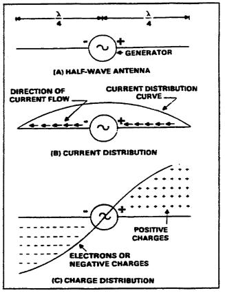
c. The current and voltage distribution on a half-wave Hertz antenna is shown in Figure 1-1. In view A, a piece of wire is cut in half and attached to the terminals of a high frequency (HF), alternating current (AC) generator. The frequency of the generator is set so each half of the wire is one-quarter wavelength of the output. The symbol for wavelength is the Greek letter lambda (D ). The result is the common dipole antenna.
Figure 1-1. Current and voltage distribution on an antenna
d. At a given moment, the generator's right side is positive and its left side is negative. A law of physics states that like charges repel each other. Consequently, electrons will flow away from the negative terminal as far as possible while the positive terminal will attract electrons. View B of Figure 1-1 shows the direction and distribution of electron flow. The distribution curve shows that most current flows in the center and none flows at the ends. The current distribution over the antenna is always the same, regardless of how much or how little current is flowing. However, current at any given point on the antenna will vary directly with the amount of voltage that the generator develops.
e. One-quarter cycle after the electrons begin to flow, the generator develops it; minimum voltage and the current decreases to zero. At that moment, the condition shown in view C of Figure 1-1 will exist. Although no current is flowing, a minimum number of electrons are at the left end of the line and a minimum number are at the right end. The charge distribution along the wire varies as the voltage of the generator varies (view C).
(1) A current flows in the antenna with an amplitude that varies with the generator voltage.
(2) A sine wave distribution of charge exists on the antenna. The charges reverse polarity every half cycle.
(3) The sine wave variation in charge magnitude lags the sine wave variation in current by one-quarter cycle.
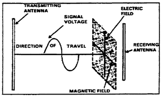
3. Radiation of electromagnetic energy. As mentioned earlier, a radio signal is generated by a transmitter, and the RF power is delivered to an antenna. Two fields are set up as the RF power reaches the antenna. One is an induction field associated with the stored energy; the other is a radiation field. The intensities of these fields are large at the antenna, and are proportional to the amount of RF power delivered to the antenna. A radio teletypewriter (RATT) using a high-powered amplitude modulation (AM) radio and a long-wire antenna has stronger fields than a small ANT/PRC-77 frequency modulation (FM) manpacked radio. Only the radiation field remains beyond a short distance from the antenna. This radiation field is made up of an electric component and a magnetic component (electromagnetic radiation). Figure 1-2 shows the components of electromagnetic waves. The electromagnetic field is responsible for the transmission and reception of electromagnetic energy through space. A radio wave is a moving electromagnetic field with components of electric intensity and magnetic intensity arranged at right angles to each other.
Figure 1-2. Components of electromagnetic waves
4. Antenna characteristics. Output from the transmitter is converted into electromagnetic energy by the antenna and radiated into space. At the receiving antenna, the electromagnetic energy is collected and converted into electrical energy and fed to the receiver.
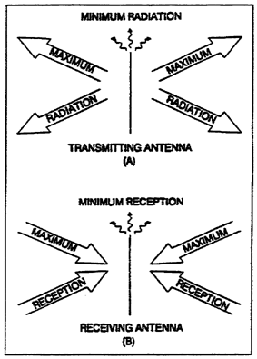
a. Antenna reciprocity is the ability to use the same antenna for transmitting and receiving. In view A of Figure 1-3, the antenna radiates a minimum amount of energy at right angles to the axis of the antennas. Note the minimum amount of radiation emanating along the axis of the antenna. If the same antenna were used as a receiving antenna (view B), it would receive best in the same directions in which it produced maximum radiation-at right angles to the axis of the antenna.
Figure 1-3. Reciprocity of antennas
b. Highly directional antennas transmit and receive more in certain directions than others. Gain is the ratio between the amount of energy transmitted or received in these directions compared to the energy that would be transmitted or received if the antenna were not directional. Antenna gain also gives directional antennas greater transmission range than omnidirectional antennas for an equal signal.
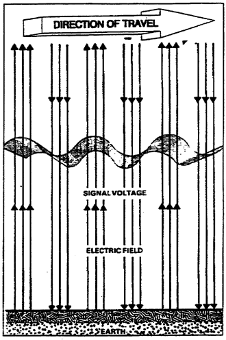
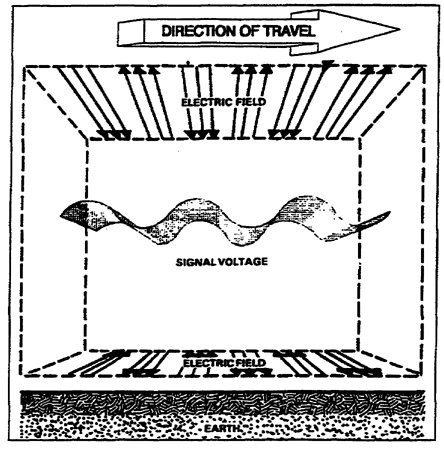
c. A radiated field is composed of electric and magnetic lines of force which are called fields. A radiated wave's polarization is determined by the direction of the electric field in relation to the Earth. If the lines of electric force are at right angles to the Earth's surface, the wave is vertically polarized (Figure 1-4). If the lines of electric force are parallel to the Earth's surface, the wave is horizontally polarized, as shown in Figure 1-5. When a single-wire antenna is used to extract (receive) energy from a passing radio wave, maximum pickup results when the antenna is oriented so it lies in the same direction as the electric field component. Thus, a vertical antenna is used for efficient reception of vertically polarized waves, and a horizontal antenna is used for horizontally polarized waves. In some cases, the field rotates as the waves travel through space. When this occurs, both the horizontal and vertical components of the field exist, and the wave has elliptical polarization.
Figure 1-4. Vertically polarized signal
Figure 1-5. Horizontally polarized signal
d. For ground-wave transmissions, medium and low frequencies are used, and the antennas need to be vertically polarized. This allows the radio wave to travel a considerable distance along the ground surface with minimum absorption by the Earth. Horizontal polarization cannot be used at these frequencies because the electric lines run parallel to and touch the Earth. As a horizontal wave travels across the surface, it is attenuated and is not propagated very far. At high frequencies, either horizontal or vertical polarization may be used with sky wave transmission. This is because the sky wave arrives at the receiving antenna elliptically polarized. This polarization is a result of the wave traveling obliquely through the Earth's magnetic field and striking the ionosphere. Thus, the transmitting and receiving antennas can be either horizontal or vertical. When using frequencies in the ultra high frequency (UHF) or very high frequency (VHF) range, either horizontal or vertical polarization is acceptable. But, you must ensure that the transmitting and receiving antennas have the same polarization.
e. An advantage of vertical polarization is that vertical half-wave and quarter-wave antennas can provide omnidirectional communications. This helps when communicating from a moving vehicle, although it radiates equally to both enemy and friendly forces. Another advantage, when using vertical polarization, is that less inference is picked up from strong VHF and UHF broadcast transmissions (television and FM radio). This is because those systems use horizontal polarization.
f. Horizontally polarized antennas do have certain advantages and are preferred at high frequencies. A horizontal antenna is less likely to pick up man-made interference (such as those produced by automobile ignition systems and electrical appliances), which is usually vertically polarized. A second advantage is that there is less absorption of radiated energy by buildings or wiring when a horizontal antenna is used. In addition, a simple horizontal half-wave antenna is bi-directional which is useful in minimizing interference from certain directions. Finally, horizontally polarized waves suffer lower losses than vertically polarized waves, especially above 100 MHz. Antennas located near dense rests should be horizontally polarized.
g. Directionality is the characteristic of an antenna that allows it to transmit and receive in a specific direction. Other stations operating on the same or nearby frequencies may interfere with the desired signal and make reception difficult or impossible. Reception of a desired signal can be improved by using directional antennas. Horizontal half-wave antennas accept radio signals from all directions, with the strongest reception being received in a line perpendicular to the antenna (broadside), and the weakest reception being received from the direction of the antenna's ends. Changing the antenna's axis so either end points directly toward the interfering source may eliminate or reduce interference. Directional transmitting antennas concentrate radiation in a given direction and minimize radiation in other directions. A directional antenna may be used to lessen enemy interception and interference with friendly stations.
h. Since antennas are erected over the Earth and not out in free space, except for those on satellites, the ground's presence alters the free space radiation patterns of antennas. The ground also affects some of the electrical characteristics of an antenna. It has the greatest effect on those antennas that must be mounted relatively close to the ground, in terms of wavelength. For example, medium and high frequency antennas, elevated above the ground by only a fraction of a wavelength, will have radiation patterns that are quite different from the free-space patterns.
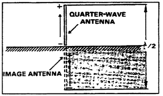
i. Grounded antenna theory. The ground, a good conductor for medium and low frequencies, acts as a large mirror for the radiated energy. This results in the ground reflecting a large amount of energy that is radiated downward from an antenna mounted over it. Using this characteristic of the ground, an antenna only a quarter-wavelength long can be made into the equivalent of a half-wave antenna. A quarter-wave antenna erected vertically, with it's lower end connected electrically to the ground, as shown in Figure 1-6, behaves like a half-wave antenna. Under these conditions, the ground takes the place of the missing quarter-wavelength, and the reflections supply that part of the radiated energy that normally would be supplied by the lower half of an ungrounded half-wave antenna.
Figure 1-6. Quarter-wave antenna connected to ground
j. There are several types of grounds.
(1) When grounded antennas are used, the ground must have as high a conductivity as possible. This reduces ground losses and provides the best possible reflecting surface for the down-going radiated energy from the antenna. At low and medium frequencies, the ground acts as a sufficiently good conductor. Thus, the ground connection must be made in such a way as to introduce the least possible amount of resistance to ground. At higher frequencies, artificial grounds constructed of large metal surfaces are common.
(2) The ground connections take many forms, depending on the type of installation and the loss that can be tolerated. In many simple field installations, the ground connection is made by driving one or more metal rods into the soil. When more satisfactory arrangements cannot be made, ground leads can be connected to existing devices that are grounded. Metal structures or underground pipe systems are commonly used as ground connections. In an emergency, a ground connection can be made by forcing one or more bayonets into the soil.
(3) When an antenna must be erected over soil with low conductivity, treat the soil with substances that are highly conductive, when in solution, to reduce the soil's resistance. Some of these substances, listed in order of preference, are sodium chloride (common salt), calcium chloride, copper sulphate (blue vitriol), magnesium sulphate (Epsom salt), and potassium nitrate (saltpeter). The amount required depends on the type of soil and its moisture content. Please note that when these substances are used, they must not get into nearby drinking water supplies.
(4) For simple installations, a single ground rod can be fabricated in the field from pipe or conduit. A low resistance connection must be made between the ground wire and the ground rod. The rod should be cleaned thoroughly by scraping and sandpapering at the point where the connection is to be made, and a clean ground clamp should be installed. A ground wire can then be soldered or joined to the clamp. This joint should be covered with tape to prevent an increase in resistance due to oxidation.
k. When an actual ground connection cannot be used because of the high resistance of the soil or because a large buried ground system is not practical, a counterpoise can be used to replace the usual direct ground connection.
(1) A counterpoise consists of a device made of wire that is erected a short distance above the ground and insulated from it. The counterpoise's size should be at least equal to or larger than the size of the antenna.
(2) When the antenna is mounted vertically, the counterpoise should be made into a simple geometric pattern; perfect symmetry is not required. The counterpoise acts as an artificial ground that helps to produce the required radiation pattern. Figure 1-7 shows an RC-292 ground-plane antenna. The three antenna elements pointing downward provide the counterpoise for this antenna.
Figure 1-7. RC-292 ground-plane antenna
(3) In some VHF antenna installations on vehicles, the metal roof of the vehicle or shelter is used as a counterpoise for the antenna. Small counterpoises of metal mesh are sometimes used with special VHF antennas that must be located a considerable distance above the ground.
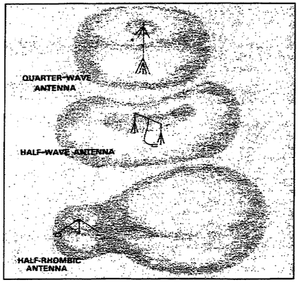
l. Depending on the type of antenna used, radio energy radiated by an antenna forms an electromagnetic field that has a definite pattern. A radiation pattern shows the directional characteristics of an antenna. A vertical antenna (Figure 1-7) or a whip antenna on a vehicle radiates energy equally in all directions (omnidirectionally). A horizontal antenna, like those used with RATT systems, is bidirectional. Unidirectional antennas radiate energy in only one direction. These radiation patterns do not provide perfectly symmetrical coverage. There are distortions in the patterns (back lobes and side lobes) which are attributed to the antenna's physical characteristics and nearby obstructions or terrain features. Three common radiation patterns are shown in Figure 1-8. The upper pattern is that of a quarter-wave vertical antenna. Note its omnidirectional pattern. The center pattern shows a half-wave horizontal pattern, located one-half wavelength above the ground. RATT rigs use these long-wire or doublet antennas. The bottom pattern is that of a vertical half-rhombic antenna that radiates in one direction.
Figure 1-8. Radiation patterns from quarter-wave, half-wave, and vertical half-rhombic antennas.
m. An antenna's length is related to the wavelength of the frequency used. An antenna has both a physical length and an electrical length, and the two are never the same. Use the following formulas to calculate the physical length of a half-wave long-wire antenna.
As an example, a radio operator must design a long-wire (doublet) antenna for use with an AM radio, tuned to 12 MHz. Using the formula:
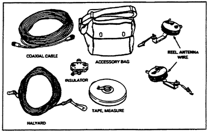
The operator must measure the antenna 39 feet in length to operate at a frequency of 12 MHz. The AN/GRA-50 antenna group is the most common antenna assembly used to erect a long-wire antenna. Figure 1-9 shows the AN/GRA-50's component parts. A very useful component is the tape measure, which is graduated in both feet and meters. An operator lays out the antenna wire and measures the required length. The electrical length of an antenna must be compatible with the frequency used. When you change the frequency on the radio, the antenna matching unit mounted on the vehicle will automatically change the electrical length of the whip antenna.
Figure 1-9. AN/GRA-50 antenna group
5. Summary. In this lesson, you learned about the theory of antennas, including the principles of antenna radiation, the characteristics of antennas, and the formulas used in antenna design.
a. Current flows in the antenna with an amplitude that varies with the generator voltage.
b. Two fields are established at an antenna (the induction field and the radiation field). The radiation field is made up of an electric component and a magnetic component (electromagnetic).
c. Output from a transmitter is released at the antenna in the form of electromagnetic energy. At the receiving antenna, electromagnetic energy is collected and converted into electrical energy, where it is fed to the radio receiver.
d. Antenna reciprocity is the feature that allows an antenna to both transmit and receive radio signals.
e. Antenna gain is the ratio between the amount of energy propagated in certain directions, compared to the energy that would be propagated if the antenna were not directional. Antenna gain also gives directional antennas greater transmission range than omnidirectional antennas for an equal signal.
f. The orientation of a radio wave's electric field in relation to the Earth is known as its polarization. A radiated wave can be vertically, horizontally, or elliptically polarized.
g. Directionality is the characteristic of an antenna that allows it to transmit and receive in a specific direction.
h. The earth (ground) can be used as a conductor for radio frequencies.
i. A counterpoise is a conductor or system of conductors used as a substitute for a ground in an antenna system.
j. Radiation patterns can be omnidirectional (all directions), bidirectional (two directions), or unidirectional (one direction).
k. To calculate the physical length of a half-wave long-wire antenna, use the following formulas:


