|
RDL Homepage |
Table of Contents |
Document Information |
Download Instructions |
LESSON 2
REMBASS EQUIPMENT
OVERVIEW
TASK DESCRIPTION:
In this lesson you will learn the basic characteristics of the different pieces of REMBASS equipment.
LEARNING OBJECTIVE:
| ACTIONS: | Describe the various pieces of REMBASS equipment and the functions they serve. |
| CONDITIONS: | You will be given narrative information and illustrations from FM 34-10-1. |
| STANDARDS: | Describe the functions and characteristics of the different pieces of REMBASS equipment. |
| REFERENCES: | The material contained in this lesson was derived from the following publications: FM 34-10-1 |
INTRODUCTION
Upon completion of this lesson, you will be able to describe the various pieces of equipment in the REMBASS system and the functions they serve.
PART A - Sensors
There are three sensors in the REMBASS system. They are the Magnetic sensor (DT-561), the Seismic Acoustic sensor (DT-562), and the Infrared Passive (DT-565).
Each sensor consists of a transducer, transmitter, and battery. There are many similarities between the sensors. The transmitter module, encoder board, battery, antenna, and housing assembly are identical. They use the same standard communication format for data transmission output, and all sensors have a self disabling and anti-tampering feature. In fact, when the transducer is not connected, the only way to tell the sensors apart is by reading the data plate.
The sensors are implanted in strings. A string can be tailored to the threat and terrain. Normally a string consists of one of each type sensor. A string must be arranged so that the target passes within the detection range of each sensor. It takes experience for an operator to know exactly how the string should be arranged. Strings should be placed at choke points whenever possible to ensure that the targets pass within the detection ranges. High speed avenues of approach and key roads and trails are also good locations for strings. A string implanted without thought of its location, is a waste of equipment, time, and troops.
(1) MAGNETIC SENSOR DT-561/GSQ (See Figure 2-1)
The magnetic (MAG) sensor uses a passive magnetic technique to detect targets, and determine direction. The direction is relative to the transducer (movement from left to right or right to left). The MAG has two identification (ID) codes. If a target is moving left to right the first ID code will be transmitted. If a target is moving right to left the second ID code will be transmitted. The MAG will only detect ferrous metal (iron) that passes within the detection range. The MAG will not classify a target. Only a "detect" (-) will be transmitted with the appropriate sensor ID code. The MAG is used as a count indicator (the number of detections are the approximate number of targets) for vehicles. The MAG is not generally used for counting personnel due to its limited range and the fact that they must be armed.
GENERAL TECHNICAL CHARACTERISTICS
| Weight: | Sensor with battery 2.95 kilograms (6.5 pounds) | |
| Number of channels: | 599 (593 usable) excluding 208, 211, 267, 342, 345, 354 | |
| ID codes (each channel): | 63 (codes 01 through 63) | |
| Sensor signal output: | 2 Watts nominal | |
| Frequency range: | 138-153 megahertz (MHz) | |
| Channel spacing: | 25 kilohertz (KHz) apart | |
| Detection ranges: | Personnel Wheeled vehicle Tracked vehicle |
3 meters 15 meters 25 meters |
| Power source: | Battery BA-5598/U | |
| Battery life: | 1,000 activations a day for 30 days | |
| Reference: | TM 11-6350-220-12 | |
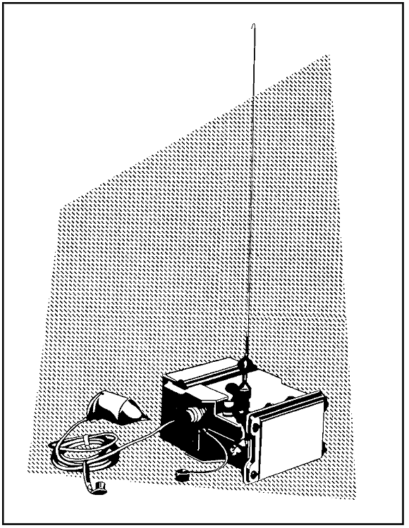
Figure 2-1. Magnetic Sensor DT-561/GSQ.
(2) SEISMIC-ACOUSTIC SENSOR DT-562/GSQ (See Figure 2-2)
The seismic-acoustic (SA) sensor detects and classifies targets. This is the most vital sensor in a string, without it the type of target would be unknown. It will send its ID code plus a P (personnel), W (wheeled vehicle), T (tracked vehicle), V (vehicle, type unknown), or a (-) (detect). The sensor works by detecting vibrations in the ground and analyzing acoustic signals. The SA will activate every 10 seconds as long as the target is within its detection range. Soil composition affects the detection range of the SA. To help compensate for this, its gain sensitivity can be programmed High, Medium, or Low.
GENERAL TECHNICAL CHARACTERISTICS
| Weight: | Sensor with battery 2.95 kilograms (6.5 pounds) | |
| Number of channels: | 599 (593 usable) excluding 208, 211, 267, 342, 345, 354 | |
| ID codes (each channel): | 63 (codes 01 through 63) | |
| Sensor signal output: | 2 Watts nominal | |
| Frequency range: | 138-153 megahertz (MHz) | |
| Channel spacing: | 25 kilohertz (KHz) apart | |
| Detection ranges: | Personnel Wheeled vehicle Tracked vehicle |
50 meters 250 meters 350 meters |
| Power source: | Battery BA-5598/U | |
| Battery life: | 1,000 activations a day for 30 days | |
| Reference: | TM 11-6350-220-12 | |
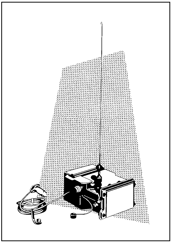
Figure 2-2. Seismic-Acoustic Sensor DT-562/GSQ.
(3) INFRARED PASSIVE SENSOR DT-565/GSQ (See Figure 2-3)
The infrared passive (IP) sensor detects targets by responding to a 1.5 degree Celsius change in ambient temperature. The IP gives direction relative to the transducer (movement from left to right or right to left). The IP has two ID codes. If a target is moving from left to right, the first ID code will be transmitted. If a target is moving from right to left, the second ID code will be transmitted. The IP is a count indicator for personnel (the number of activations is the approximate number of targets). It is generally not used for vehicles because a single vehicle can cause the IP to send multiple activations (it may activate once on the engine compartment, once on the exhaust, and several times on dust trails). The IP cannot classify targets; only a detect (-) will be transmitted. The IP is the only sensor which has the transducer above ground. The IP must have uninterrupted line of sight from the transducer to the target area.
GENERAL TECHNICAL CHARACTERISTICS
| Weight: | Sensor with battery 2.95 kilograms (6.5 pounds) | |
| Number of channels: | 599 (593 usable) excluding 208, 211, 267, 342, 345, 354 | |
| ID codes (each channel): | 63 (codes 01 through 63) | |
| Sensor signal output: | 2 Watts nominal | |
| Frequency range: | 138-153 megahertz (MHz) | |
| Channel spacing: | 25 kilohertz (KHz) apart | |
| Detection ranges: | Personnel Vehicles (wheeled and tracked) |
3-20 meters 3-50 meters |
| Power source: | Battery BA-5598/U | |
| Battery life: | 1,000 activations a day for 30 days | |
| Reference: | TM 11-6350-220-12 | |
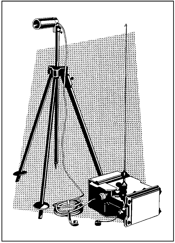
Figure 2-3. Infrared Passive Sensor DT-565/GSQ.
PART B. - RADIO REPEATER RT-1175/GSQ (See Figure 2-4)
The radio repeater (commonly called the repeater) relays sensor transmissions to the monitoring site. This is often necessary because REMBASS transmissions require RLOS. As many repeaters as necessary may be used to accomplish this. The repeater operates by receiving REMBASS transmissions on one channel and then transmitting them on another channel. This provides system flexibility to operate over and around terrain features which would block RLOS. The repeater has only one ID code, which is 64. This ID code is reserved solely for repeaters. The repeater will send a message of 64 over 1 every 84 minutes to verify the repeater is still operational. A message of 64 over 8 will be sent when the repeater receives electromagnetic interference. The repeater is capable of being operated on an airborne platform to extend the range to 100 KM.
GENERAL TECHNICAL CHARACTERISTICS
| Weight: | Repeater with 6 batteries 18 kilograms (40 pounds) | |
| ID codes (each channel): | 1 per channel (64) | |
| Transmitter power output: | 2 Watts nominal | |
| Antenna type: | Radial- omnidirectional | |
| Frequency range: | 138-153 megahertz (MHz) | |
| Channel spacing: | 25 kilohertz (KHz) apart | |
| Number of channels: | 599 (593 usable) excluding 208, 211, 267, 342, 345, 354 | |
| Power source: | Primary- Battery BA-5590/U Alternate- PP-8080/GSQ (power supply) |
|
| Transmission range: | Ground to ground Ground to air |
- 15 KM - 100 KM |
| Battery life: | 16,000 activations a day for 30 days (with six batteries) | |
| Reference: | TM 11-5820-872-12 | |
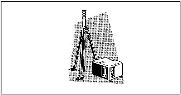
Figure 2-4. Radio Repeater RT-1175/GSQ.
PART C. - CODE PROGRAMMER C-10434/GSQ (See Figure 2-5)
The code programmer is used to program system parameters into the sensors and repeaters. The operator uses it to program into the equipment the ID code(s), mission life, mode (arm or test), channel, and gain (SA sensor only). It also conditions the batteries in the equipment. The code programmer receives its power from the equipment being programmed. The sensors and repeaters cannot be used without first being programmed.
GENERAL TECHNICAL CHARACTERISTICS
| Weight: | 1.1 Kilogram (2.5 pounds) | |
| Number of channels: | 599 (593 usable) excluding 208, 211, 267, 342, 345, 354 | |
| Power source: | The code programmer receives its power from the power source of the equipment being programmed | |
| Reference: | TM 11-6350-288-12 | |
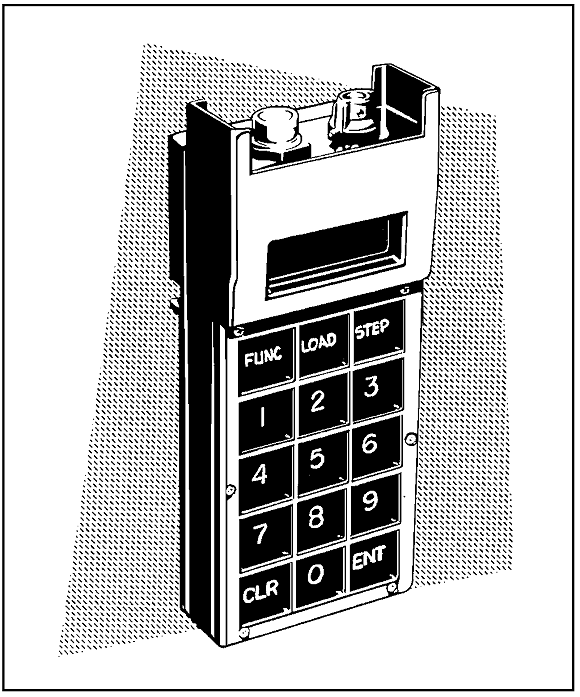
Figure 2-5. Code Programmer C-10434/GSQ.
PART D. - ANTENNA GROUP OE-239/GSQ (See Figure 2-6)
The antenna group is used to receive transmissions from sensors and repeaters. It has a radio frequency (RF) amplifier to provide the SMS with adequate signal strength to receive transmissions from extended ranges. The antenna group is normally used when the SMS cannot receive all sensors and repeaters with the blade antenna, or when at the monitoring site for an extended period. The RF amplifier is powered by a battery in the antenna coupler. A total of four SMSs may be connected to one antenna by using the antenna coupler.
GENERAL TECHNICAL CHARACTERISTICS
| Weight: | Antenna group - 20 kilograms (44 pounds) Cable - 12.5 kilograms (27.6 pounds) |
|
| Antenna type: | Omnidirectional Collinear Array, 50 ohms impedance | |
| Frequency range: | 138-153 megahertz (MHz) | |
| Channel spacing: | 25 kilohertz (KHz) apart | |
| Antenna coupler: | RF input and four RF outputs | |
| Power source: | Battery BA-5590/U | |
| Battery life: | 15 hours minimum | |
| Reference: | TM 11-5820-867-12 | |
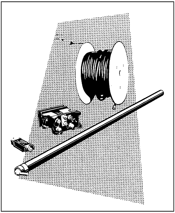
Figure 2-6. Antenna Group OE-239/GSQ.
PART E. - RADIO FREQUENCY MONITOR R-2016/GSQ (See Figure 2-7)
The radio frequency monitor is a portable monitoring set (commonly called PMS). It is a single channel receiver used to receive REMBASS transmissions. It has ten temporary visual displays (TVDs) to display REMBASS activations. The PMS will display the ID code and a detect or classification (SA sensor only) from the sensor. Each TVD will remain on for six seconds after receiving an activation. The PMS has an adjustable audio alarm to alert the operator of an activation. The primary use of the PMS is for verification of REMBASS sensor and repeater operations during the initial implant. It may also be used as an alternate monitor if the SMS becomes inoperative.
GENERAL TECHNICAL CHARACTERISTICS
| Weight: | PMS with battery 2.96 kilograms (6.52 pounds) | |
| Number of channels: | 599 (593 usable) excluding 208, 211, 267, 342, 345, 354 | |
| ID codes (each channel): | 64 per channel | |
| Sensor signal readout: | TVD, audio alarm | |
| Frequency range: | 138-153 MHz | |
| Channel spacing: | 25 KHz apart | |
| Power source: | Battery BA-5598/U | |
| Battery life: | 168 hours of continuous operation | |
| Reference: | TM 11-5820-870-12 | |
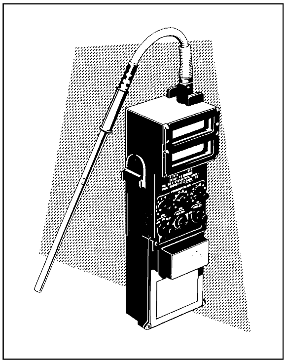
Figure 2-7. Radio Frequency Monitor R-2016/GSQ.
PART F. - SENSOR MONITORING SET AN/GSQ-187 (See Figure 2-8)
The sensor monitoring set (SMS) is the primary monitoring device for the REMBASS system. It has two single channel receivers capable of receiving from both channels simultaneously. It displays activations on TVDs and a hard copy (printer paper). There are ten TVDs, each one will display an activation for six seconds. The printer paper has 60 columns (called PENS). Each PEN is dedicated to a specific sensor or repeater ID. Up to a maximum of 60 IDs may be programmed into the SMS. The printer provides a hard copy of activations and classifications (P, V, W, T). The SMS can be used with its own blade antenna or the antenna group OE-239. The keypad is used to program and test the SMS.
GENERAL TECHNICAL CHARACTERISTICS
| Weight: | SMS with two batteries 20 kilograms (44 pounds) SMS with power supply PP-8080 23 kilograms (51 pounds) |
|
| Number of channels: | 599 (593 usable) excluding 208, 211, 267, 342, 345, 354 | |
| ID codes (each channel): | 64 per channel | |
| Sensor signal readout: | TVD, audio alarm, and printer | |
| Frequency range: | 138-153 MHz | |
| Frequency spacing: | 25 KHz apart | |
| Power source: | Primary - BA-5590/U (two each) Alternate - PP-8080/GSQ power supply |
|
| Battery life: | 15 hour minimum | |
| Printer: | Thermal printing, 60 column (PENS), two speed: Low 15 inches per hour, High 30 inches per hour. |
|
| Reference: | TM 11-5820-867-12 | |
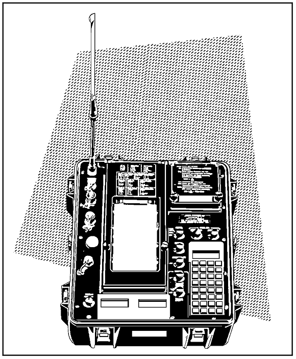
Figure 2-8. Sensor Monitoring Set AN/GSQ-187.
PART G. - POWER SUPPLY PP-8080/GSQ (See Figure 2-9)
The power supply can be used as a power source for the repeater and SMS in place of batteries. It can be connected to a 115 or 220 volt alternate current (AC) outlet or a 24 volt direct current (DC) source. The PP-8080/GSQ coverts the 115 or 220 volt AC or 24 volt DC power to the 12 volts DC needed to power the SMS and repeater. The power supply helps conserve batteries when the SMS is located in a TOC and it is connected to a power source inside the TOC.
GENERAL TECHNICAL CHARACTERISTICS
| Weight: | 3.7 kilograms (8.1 pounds) | |
| Reference: | TM 11-6130-460-13 | |
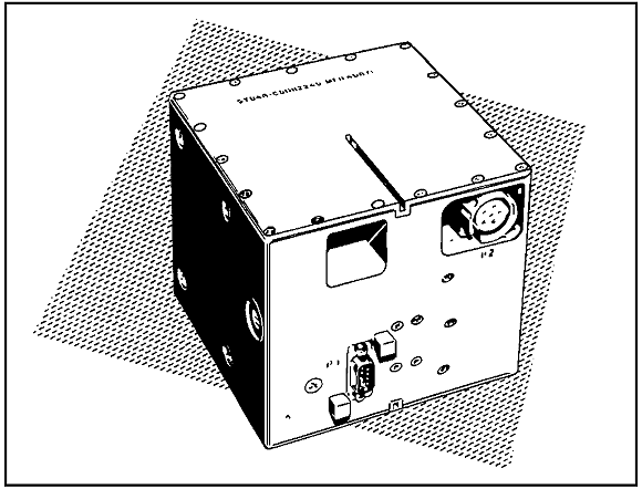
Figure 2-9. Power Supply PP-8080/GSQ.
Practice Exercise

