|
RDL Homepage |
Table of Contents |
Document Information |
Download Instructions |
LESSON 3
FIRE SUPPORT PLANNING
TASK
Identify target terms, procedures and techniques for targeting, and the fundamentals of fire support planning and coordination.
CONDITIONS
Given the subcourse material for this lesson, a training scenario and extracts, as applicable, the student will complete the practice exercise at the end of this lesson.
STANDARD
The student will demonstrate his comprehension and knowledge of the task by identifying target terms, procedures and techniques for targeting, and the fundamentals of fire support planning and coordination.
REFERENCES
GENERAL
To prepare fire support plans, the FSCOORD at all levels must understand the terminology and techniques used in targeting and fire planning.
The word "target" is the most fundamental term used in fire support planning. In fire support operations, a target is any personnel, materiel, or piece of terrain that is designated and numbered for future reference and or firing.
Learning Event 1: THE STUDENT WILL DEMONSTRATE HIS COMPREHENSION AND KNOWLEDGE OF THE TASK BY IDENTIFYING TARGET TERMS AND TARGETING TECHNIQUES USED IN FIRE SUPPORT PLANNING.
TARGET CLASSIFICATION
Each target can be classified as either a planned target or a target of opportunity. Each type of target will be discussed separately.
Target of Opportunity
A target of opportunity is a target that appears during combat. It can be reached by ground, naval, or aircraft fire. No previous plans for fire have been prearranged against the target.
Planned Target
A planned target is one for which fire is prearranged. The degree of prearrangement varies, but some prior arrangement has been made to facilitate its engagement.
Individually, planned targets may be further subdivided into scheduled, on-call, and priority targets.
Scheduled Target. A scheduled target is a planned target on which fire is to be delivered at a specified time. The time may be related to an H-hour or another time reference. However, once the reference has been established, the scheduled target will have a definite time sequence.
On-Call Target. An on-call target is a planned target other than a scheduled target on which fire is to be delivered when requested. The on-call target requires less reaction time than a target of opportunity.
Priority Target
A priority target is a target on which the delivery of fires takes precedence over all other fires for the designated firing unit or element.
The supported commander designates priority targets. He provides the FSCOORD specific guidance as to when targets will become priority targets and when they no longer will be priority targets. The commander should state the desired effects on targets and any special types of ammunition to be used. When they are not engaged in a fire mission, firing units lay their weapons on assigned priority targets. Generally, each priority target has a fire unit laid on it. However, in dedicated battery operations, designated weapons may be assigned priority targets. This allows the rest of the battery to fire in support of the maneuvering unit. An example of a priority target in a defensive situation is final protective fires. Final protective fires will be discussed later in this lesson.
The use of symbols in the preparation of maps, charts, and overlays is basic military procedure. Complete information on general military symbols is in FM 101-5-1.
TARGET SYMBOLS
The symbols most common to the fire support planner are those relating to targets and fire support coordination measures. Figure 7, presents the various types of targets and their appropriate symbols.
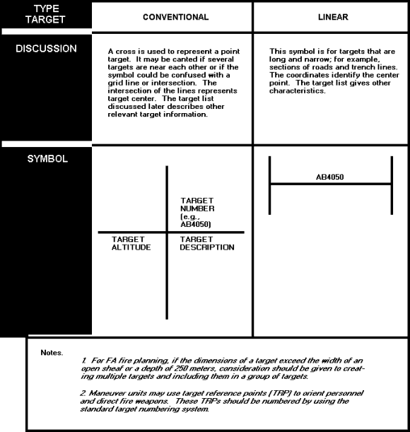
FIGURE 7. TARGET SYMBOLS
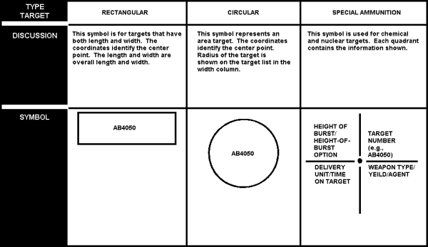
FIGURE 7A. TARGET SYMBOLS
TARGET NUMBERING
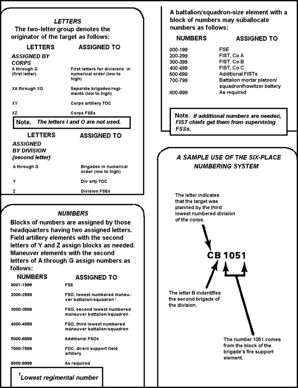
To designate non-nuclear targets for fire support operations, the Army adheres to the provisions of STANAG 2147 and QSTAG 221. Target designators consist of two letters followed by four numerals; for example, AA1000. This numbering system is used for each corps-size force. Table 10, explains the assignment of letters and numbers to form a target designator.
TABLE 10. LETTERS
Normally, nuclear and chemical targets are not assigned a special block of target numbers. A target should be assigned a number when it is received at a fire planning agency. If a target is selected for attack, the most appropriate means of attacking the target will be used (nuclear, chemical, or conventional) as determined by target analysis. That analysis is guided by the commander's attack guidance and other factors, such as nature of the target and the munitions available.
Learning Event 2: THE STUDENT WILL DEMONSTRATE HIS COMPREHENSION AND KNOWLEDGE OF THE TASK BY IDENTIFYING ARTILLERY CANNON AND ROCKET CHARACTERISTICS.
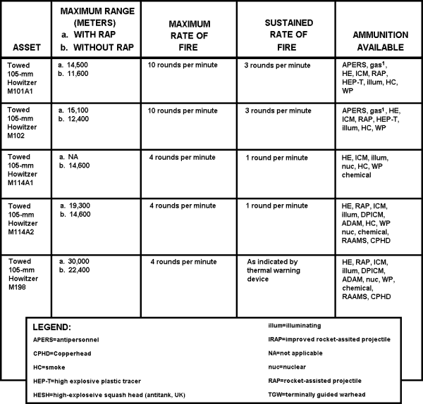
When planning and scheduling weapons for fire missions, it is important that you schedule the proper weapon for the job to be performed. Some weapons may not have adequate range to fire at targets in all phases of the schedule. Other weapons may not have the necessary sustained or maximum rate of fire to properly cover the target area. Still other weapons may not be capable of firing the proper type of ammunition for the mission. Tables 12 and 12A, list the characteristics of artillery cannons and rockets. The data presented should be used in planning and scheduling the right weapons for the mission to be performed.
TABLE 12. ARTILLERY CANNON AND ROCKET CHARACTERISTICS
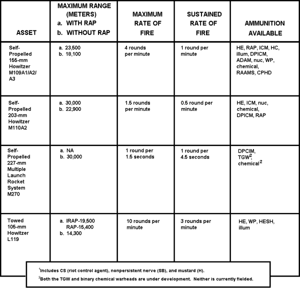
TABLE 12A. ARTILLERY AND ROCKET CHARACTERISTICS (continued)
You should now be familiar with the characteristics of the various artillery cannons and rockets. The next learning event will introduce you to the necessary planning criteria and implementation procedures for conducting a final protective fire.
Learning Event 3: THE STUDENT WILL DEMONSTRATE HIS COMPREHENSION AND KNOWLEDGE OF THE TASK BY IDENTIFYING THE PLANNING CRITERIA AND IMPLEMENTING PROCEDURES FOR A FINAL PROTECTIVE FIRE.
PLANNING FIRES
Fire planning, like fire support planning, is a continuous process conducted by FSCOORDs at all levels to ensure that fires support the commander's operation plan. Fire is prearranged on these targets to ensure responsive engagement when requested. Although some of the planned fires apply to offensive or defensive actions only, others are appropriate to all types of operations and levels of combat.
When operating as part of a multinational force, the US will implement STANAG 2031/QSTAG 515. The provisions of ratified STANAG 2031/QSTAG 515 have been incorporated throughout the discussions of target lists, target overlays, artillery fire plans, and artillery quick-fire plans in this lesson and elsewhere in this publication.
Procedures for fire planning vary, depending on whether the supporting unit is equipped with automated equipment. The fire planning techniques for final protective fires, fires using smoke, and schedules of fire are described in the following paragraphs.
FINAL PROTECTIVE FIRES
FPFs are immediately available fires designated to create a barrier to impede enemy movement across defensive lines or areas. They are integrated with the commander's defensive plans and are intended for use primarily against dismounted infantry. Maneuver brigade commanders allocate FPFs to maneuver battalions, which in turn allocate them to their companies.
FPFs are allocated one per firing unit (field artillery), one per section (81-mm mortars) or one per platoon (107-mm mortars). When they are not engaged in another fire mission, weapons are laid on firing data for final protective fires. This ensures immediate responses to calls for final protective fires.
The shape and pattern of these fires may be varied to suit the tactical situation on the basis of the support company commander's desires. Authority to call for the FPFs is vested in the supported company commander or platoon leader in whose area they are located. On the target list work sheet, a target is designated as the FPF target by placing the letters "FPF" in the REMARKS column space for that particular target. FPF targets are designated by target number.
Size of FPF
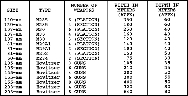
The size of the FPF depends on the type of weapon used to deliver the fire. Table 13, below, shows the size of the protective fire area each weapon is capable of delivering.
TABLE 13. FPF PLANNING
Location of FPF
The location of the FPF normally is designated by the maneuver commander for whom it is being planned. It may be any distance from the friendly position that supports the current tactical situation which is within range of organic direct fire weapons. This is normally within 200 to 400 meters (danger close). The importance of accurate defensive fires and the danger close situation require that each weapon firing the FPF be adjusted into place, if possible.
In using a battery computer system (BCS) or a manual fire direction center, the call for fire is similar to the normal call for fire in an adjust fire mission, except that--
- If an adjustment is to be done, the target location initially sent is not the location of the center of the FPF. It is a grid point a safe distance (400 to 600 meters) from the location of friendly troops. Because this grid is part of a final defensive plan, it should be encoded. The attitude or direction of the long axis of the FPF is announced.
- In place of a target description, FINAL PROTECTIVE FIRES is announced.
- DANGER CLOSE is announced in the method of engagement.
The firing unit fires one volley centered on the initial grid sent by the observer. Assume that the rounds impact as shown in Figure 10 below. The observer begins his adjustment with the flank piece impacting closest to the FPF line (in this case, Number 1). Recall that creeping fire must be used because of the danger close situation. Corrections of 50 meters or less are not fired.

FIGURE 10. ADJUSTMENT OF THE FPF
Once the first gun is adjusted, the observer sends NUMBER 2, REPEAT and adjusts each weapon in succession.
NOTE: If the FDC is using a computer (BCS or BUCS), only the center weapon will be adjusted onto the center grid of the FPF and the adjustment terminated.
Fuze delay should be used in adjustment to reduce the safety hazard to friendly units.
In some instances, there will not be time to "shoot in" the FPF. The observer will call in the FPF, giving the grids of the two ends or giving the center grid and attitude. If the FDC is using a battery computer systems (BCS), then length, width, and altitude or laser draw is sent.
You have just learned about the planning criteria for implementation and procedures for a final protective fire. You must now study the criteria and techniques for establishing graphic portrayal of fire support coordinating measures.
Learning Event 4: THE STUDENT WILL DEMONSTRATE HIS COMPREHENSION AND KNOWLEDGE OF THE TASK BY IDENTIFYING THE CRITERIA FOR ESTABLISHING, AND THE TECHNIQUES FOR GRAPHIC PORTRAYAL OF, FIRE SUPPORT COORDINATING MEASURES.
GENERAL
The FSCOORD coordinates all fire support impacting in the area of responsibility of his supported maneuver commander. This includes fires requested by the supported unit. He ensures that fire support will not jeopardize troop safety, will interface with other fire support means, and will not disrupt adjacent unit operations. Fire support coordinating measures help him in those efforts. They are designed to facilitate the rapid engagement of targets and at the same time provide safeguards for friendly forces.
ESTABLISHMENT AND GRAPHIC PORTRAYAL
All fire support coordinating measures, except boundaries, are established by the supported maneuver commander on the basis of recommendations by the FSCOORD. The FSCOORD's recommendations are based on the force commander's guidance, and anticipated enemy actions.
Once established, coordinating measures are displayed on maps, firing charts, and overlays and are stored in computers. Graphic portrayal includes, as a minimum, the abbreviation for the measure, the establishing headquarters, and the effective date-time group (DTG). Often, the date-time group will be indicated as a "from-to" time. Usually, coordinating measures are labeled at each end of a line or within the graphic, space permitting.
All fire support coordination measures are drawn and lettered in black. When only one color can be used (for example, in automatic data processing [ADP] graphics), restrictive measures may be coded with double lines. In this case, the outermost line is the actual boundary of the measure.
BOUNDARIES
Boundaries are used by the maneuver commander in various operations to indicate the geographical area for which a particular unit is responsible. They describe a zone of action or sector of responsibility for a maneuver unit. Boundaries are normally designated along terrain features easily recognizable on the ground. They are so situated that key terrain features and avenues of advance or approach are completely included in the area assigned to one unit. Boundaries are the basic fire support coordinating measure. As such, they are both permissive and restrictive in nature.
Boundaries are restrictive in that no fire support units may deliver fires across them unless the fires are coordinated with the force having responsibility within the boundary. Also, if a permissive fire support coordinating measure is in effect, that would allow firing without further coordination. Fires delivered near boundaries also should be coordinated with the adjacent unit. They are permissive in that a maneuver commander, unless otherwise restricted, enjoys complete freedom of fire and maneuver within his own boundaries.
Boundaries apply to both the maneuver of units and the employment of fire, to include conventional and special ammunition and their effects. Boundaries are displayed as solid black lines with the appropriate designation of the unit(s) to which the boundary applies. Proposed or planned boundaries are displayed as dashed black lines. Boundaries are also used by fire support personnel to designate the zone of fire for supporting field artillery and naval gunfire ships.
TYPES OF MEASURES
With the exception of boundaries, fire support coordinating measures are either permissive or restrictive. With the establishment of a permissive measure, no further coordination is required for the engagement of targets affected by the measure. In essence, the primary purpose of the permissive measure is to facilitate the attack of targets.
The establishment of a restrictive measure imposes certain requirements for specific coordination before the engagement of those targets affected by the measure. Therefore, the primary purpose of restrictive measures is to provide safeguards for friendly forces.
Permissive Measures
Permissive measures that may be established to save time in fire support planning are--
- Coordinated fire lines.
- Fire support coordination lines.
- Free-fire areas.
Each measure will be discussed separately in the following paragraphs.
Coordinated Fire Line (CFL). A coordinated fire line is a line beyond which conventional or improved conventional indirect fire means may fire (Figure 11). Firing may be done at any time within the zone of the establishing headquarters without additional coordination. The purpose of the CFL is to expedite the attack of targets beyond it. Usually, the CFL is established by a brigade or a division, but it may be established by a maneuver battalion.
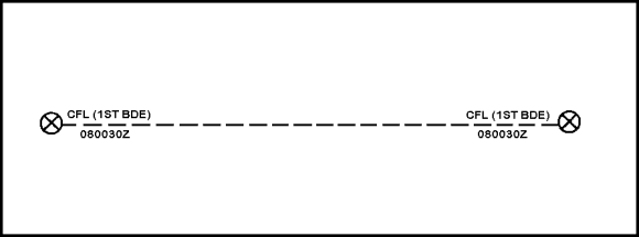
FIGURE 11. COORDINATED FIRE LINE
| NOTE: | The United States uses the coordinated fire line instead of the no-fire line (described in STANAG 2099). A US reservation to the STANAG reflects this. |
The CFL is as close to the establishing unit as is possible, without interfering with maneuver forces to open up the area beyond to fire support. Brigade CFLs may be consolidated at division level as a division CFL designated for the division zone of action. If any modifications to the brigade CFLs are considered, they must be coordinated with the brigades to ensure complete compatibility with their battle plans.
In essence, the brigade commanders establish CFLs and the division commander merely consolidates them and designates a division coordinated fire line. The CFL is graphically portrayed by a dashed black line. CFL, followed by the establishing headquarters in parentheses, is printed above the dotted line. A date-time group is printed below the line.
Locations for CFLs are disseminated by message and or overlay. They are channeled through both the maneuver and fire support channels to higher, lower, and adjacent maneuver and supporting units.
Fire Support Coordination Line (FSCL). A fire support coordination line (Figure 12) is established by the appropriate ground commander. The FSCL ensures coordination of fire that is under the control of the commander, but may affect current tactical operations. The FSCL is used to coordinate the fire of air-, ground-, and sea-launched weapons, using any type of ammunition against surface targets. It is described in STANAG 2099. The FSCL should follow well-defined terrain features.
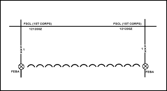
FIGURE 12. FIRE SUPPORT COORDINATION LINE
The establishment of the FSCL must be coordinated with the appropriate tactical air commander and other supporting elements. Supporting elements may attack targets forward of the FSCL without prior coordination with the ground force commander. This can only be done if the attack will not produce adverse effects on or to the rear of the line.
Attacks against surface targets short of the line must be coordinated with the appropriate ground force commander. The purpose of the FSCL is to expedite the attack of targets beyond it. Usually, the line is established by a corps (independent division) commander. It is normally placed on terrain identifiable from the air (for example, a road, railroad, or river). Dissemination is the same as that for the coordinated fire line.
When the fire support coordination line is planned, its location is sent up and down the planners chain of command, using the standard message format in Figure 13.
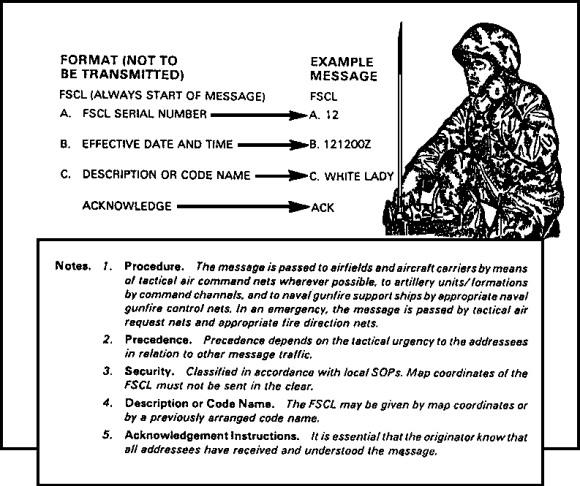
FIGURE 13. STANDARD MESSAGE FORMAT FOR FSCL
Free-Fire Area. A free-fire area (Figure 14) is a specific area into which any weapon system may fire without additional coordination with the establishing headquarters. It is used to expedite fires and facilitate the jettison of munitions when aircraft are unable to drop them on a target area.

FIGURE 14. FREE-FIRE AREA
Usually, the FFA is established by a division or higher commander. It is located on identifiable terrain, when possible, or by grid designation, when necessary. It is disseminated through both maneuver and fire support channels.
Restrictive measures
Restrictive measures that may be established include--
- Restrictive fire lines.
- Airspace coordination areas.
- No-fire areas.
- Restrictive fire areas.
Each measure will be discussed separately in the following paragraphs.
Restrictive Fire Line. The restrictive fire lines is a line established between converging friendly forces (one or both may be moving) that prohibits fires or the effects of fires across the line without coordination with the affected force (Figure 15). The purpose of the line is to prevent interference between the converging friendly forces. It is established by the commander common to the converging forces. It is on identifiable terrain, usually closer to the stationary force. Its location is disseminated in the same manner as that of a coordinated fire line.
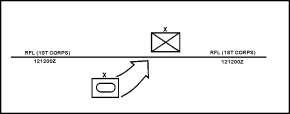
FIGURE 15. RESTRICTIVE FIRE LINE
Airspace Coordination Area (ACA). The airspace coordination area is a block of airspace in the target area in which friendly aircraft are reasonably safe from surface fires (Figure 16). Occasionally, it may be a formal measure (a three dimensional box in the sky). More often it is informal. The purpose of the ACA is to allow the simultaneous attack of targets near each other by multiple fire support means, one of which is normally air.
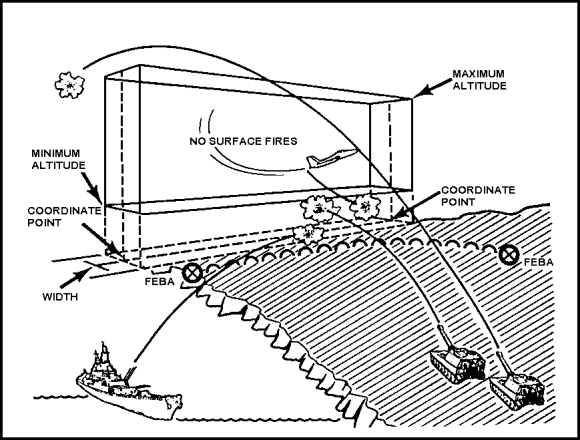
FIGURE 16. AIRSPACE COORDINATION AREA
For example, air support aircraft, field artillery, and naval gunfire can attack the same target complex. They can also attack targets close to one another while operating within the parameters of an established formal airspace coordination area. Usually, the ACA is established by a separate brigade or higher level commander.
The ACA's location is coordinated with the airspace management element. It is above the target area as recommended by an air liaison representative. The size of the area is dictated by the type of aircraft and the ordnance in use. Vital information defining the formal ACA includes minimum and maximum altitudes, a baseline designated by grid coordinates at each end, the width (either side of the baseline), and the effective times. Information concerning the area is disseminated in the same way as for the coordinated fire line.
Since implementation of the formal ACA takes a significant amount of time, an informal ACA may be established to provide safety to close air support aircraft at low levels in the target area. The informal ACA can be established by using a time and distance separation. This designates a specific terrain feature to provide separation between surface-to-surface and air-delivered fires.
An example would be to designate an east-west road as the ACA and at the same time to direct air support to stay north of the road. You must also restrict FA and naval gunfire to airspace and targets south of the road. The informal ACA may be established to task force level and is not normally displayed on maps, charts, and overlays.
No-Fire Area. A no-fire area (NFA) (Figure 17) is an area into which no fires or effects of fires are allowed. Two exceptions are--
- When the establishing headquarters approves fires temporarily within the NFA on a mission-by-mission basis.
- When an enemy force within the NFA engages a friendly force. The commander may engage the enemy to defend his force.

FIGURE 17. NO-FIRE AREA
The purpose of the NFA is to prohibit fires or their effects in the area. Usually, it is established by a division or corps on identifiable terrain, when possible. Also, it may be located by grid or by a radius (in meters) from a center point. Like other fire support coordination measures, its location is disseminated through both maneuver and fire support channels to concerned levels.
Restrictive Fire Areas. A restrictive fire area (RFA) (Figure 18) is an area in which specific restrictions are imposed. Fires that exceed those restrictions will not be delivered without coordination with the establishing headquarters. The purpose of the RFA is to regulate fires into an area according to the stated restrictions. It is established by the maneuver battalion or higher echelons of command. On occasion, an RFA may be established by a company operating independently. Usually, it is on identifiable terrain, by grid or by a radius (in meters) from a center point. Its location is disseminated in the same manner as that of the coordinated fire line. Restrictions may be shown on a map or an overlay, or reference can be made to an operations order (OPORD) that states the restrictions.

FIGURE 18. RESTRICTIVE FIRE AREAS
You have just learned about the graphic portrayal of fire support coordinating measures. The next learning event will discuss the fire support personnel's role in developing the operation order.
Learning Event 5: THE STUDENT WILL DEMONSTRATE HIS COMPREHENSION AND KNOWLEDGE OF THE TASK BY IDENTIFYING THE ELEMENTS WHICH COMPRISE, AND RESPONSIBILITIES FOR PREPARATION OF, PARAGRAPH 3a(2) AND THE FIRE SUPPORT SUBPARAGRAPH OF THE OPERATION ORDER.
This learning event describes and presents examples of the documents prepared and used by fire support personnel in tactical operations. It provides detailed information on the preparation and dissemination of the various documents required in planning and coordinating fire support.
THE FIRE SUPPORT PLAN
The commander's selected course of action, his concept of the operation, and all guidance given during the planning process form the basis for the development of the operation order (Figure 19). The OPORD merges maneuver and fires. Paragraph 3 of the OPORD outlines how the supported commander wants to use his fire support and maneuver assets. STANAG 2014 prescribes standard formats for the OPORD and its supporting documents. This learning event implements STANAG 2014 as it pertains to fire support operations and functions.

FIGURE 19. OPORD FORMAT
Responsibilities in Planning Fire Support
The FSCOORD prepares the fires portion of the Concept of Operation subparagraph of the OPORD. He also coordinates the preparation of the Fire Support subparagraph (or annex) that constitutes the fire support plan. The fire support plan includes a subparagraph for each fire support agency (means) involved in the operation.
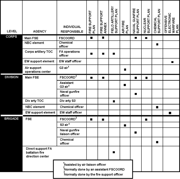
Input for these subparagraphs is prepared by the appropriate fire support representatives within the fire support element. If the Fire Support subparagraph needs amplification, the FSCOORD prepares a fire support annex. Table 14, lists the responsibilities of personnel involved in formal fire support planning.
TABLE 14. FORMAL FIRE SUPPORT PLANNING RESPONSIBILITIES
The fire support plan for a force headquarters need not totally depend on target input from subordinate elements. The fire support plan tells subordinate commanders what they are to do and what they need to know to accomplish their mission. The plan should not address items in SOPs and should not include "how to implement" instructions to individual fire support agencies. That type of information should be addressed in SOPs or in implementing instructions issued after the receipt of the fire support plan. Once the fire support plan is prepared, it is disseminated and distributed as a part of the force operation order (Figure 20 and Table 15).
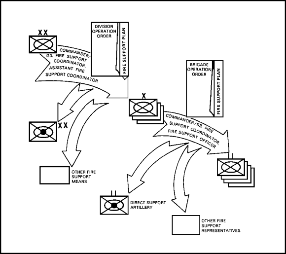
FIGURE 20. FIRE SUPPORT PLAN DISSEMINATION
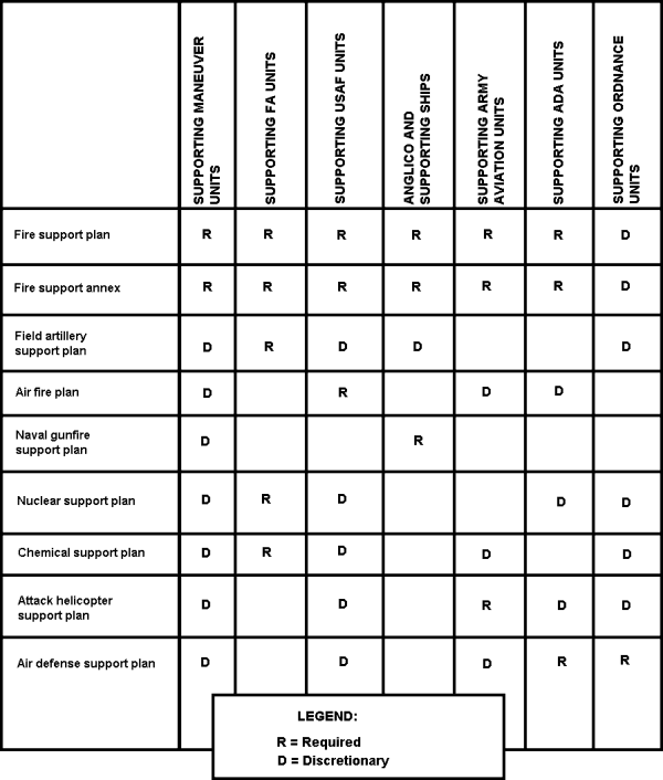
The suggested distribution of the fire support plan is presented in Table 15.
TABLE 15. SUGGESTED DISTRIBUTION OF FIRE SUPPORT PLANS
CONCLUSION
In this lesson, you have learned about targeting terms, procedures, and techniques for targeting, and the fundamentals of fire support planning and coordination, The data on characteristics of artillery cannons and rockets should allow you to select the weapon that will give you the effect desired. You have learned how to identify the planning criteria and implementing procedures for a final protective fire. This will allow elements to withdraw from enemy contact once the desired effect has been accomplished. You have also covered the graphic portrayal of fire support coordinating measures and the development of the operation order subparagraph which pertains to fire support planning.
Combining the knowledge of these lessons will enable you to plan and execute fire missions and combat the Threat forces in modern warfare.

