

|
RDL Homepage |
Table of Contents |
Document Information |
Download Instructions |
LESSON ONE
PREPARE TO EMPLOY THE TOW LAUNCHER SYSTEM
MOS Manual Tasks:
071-056-0025 - Supervise the preparation of a mounted M220 launcher firing position
071-317-2603 - Supervise the construction and camouflage of a TOW dismounted fighting position
071-316-2601 - Plan and control TOW section fires
OVERVIEW
TASK DESCRIPTION:
In this lesson, you will learn to supervise the preparation of a mounted M220 launcher firing position; to supervise the construction and camouflage of a TOW dismounted fighting position; to plan and control TOW section fires; and to inspect an anti-armor range card.
LEARNING OBJECTIVE:
| TASKS: | Identify the procedures for preparing to employ the Launcher System. |
| CONDITIONS: | You will be given information from FM 7-91 and STP 7-11H24-SM. |
| STANDARDS: | Preparing to employ the TOW Launcher System will be in accordance with FM 7-91 and STP 7-11H24-SM. |
| REFERENCES: | The material contained in this lesson was derived from the following publications; FM 7-91 and STP 7-11H24-SM. |
INTRODUCTION
Before the TOW can be employed in the field, it is necessary to prepare a mounted M220 launcher system firing position or to construct and camouflage a TOW dismounted fighting position; and to prepare an anti-armor range card. Although you will not actually perform these activities, you are responsible for supervising and inspecting them. Therefore, you need to know how each is to be performed. In addition, you must be able to plan and control TOW section fires. Lesson One of this subcourse provides instructions in each of these areas.
PART A - SUPERVISE THE PREPARATION OF A MOUNTED M220 LAUNCHER FIRING POSITION
1. Preparation.
The preparation of a firing position begins upon the occupation of a firing position and continues until the position is vacated. Preparation includes the following:
- The initial digging in.
- Range card preparation.
- Camouflaging.
2. Set Up and Dig In.
After you occupy the position and establish security, the first step in the preparation of the position is setting up and sighting the weapon system and preparing a range card. During the preparation of the position, your squad must be prepared to fight. Keeping the sector of responsibility under constant observation allows the squad to react quickly if the enemy appears before the position is completed.
3. Types of Anti-armor Positions.
Two types of Anti-armor firing positions (mounted and dismounted) are discussed in this lesson.
a. Mounted Position. The mounted firing position is characterized by a hull-down posture in which the TOW vehicle is behind either natural or constructed cover with only the TOW launcher exposed. Natural cover is best and is the easiest cover to prepare and camouflage, as shown in Figure 1-1. When natural cover is not available, hull-down positions can be excavated with engineer assistance, as shown in Figure 1-2. When hide positions are used, the primary firing positions should also be hull-down (as shown in Figure 1-3). If enemy fire is accurate, hull-down positions should be selected or constructed so that the TOW vehicle can move quickly to complete defilade. Routes into and out of hull-down positions should also have complete defilade.
b. Dismounted Position. The dismounted firing position is discussed in Part B of Lesson One of this subcourse.
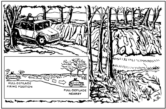
Figure 1-1. Natural Hull-Down Position.
4. Camouflage and Conceal the Firing Position.
Once the position is dug, you must camouflage it.
Use any of the following natural materials to camouflage the position:
- Sod.
- Leaves.
- Brush.
- Grass.
- Overturned dirt.
- Any other natural material.
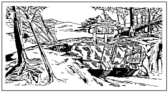
Figure 1-2. Excavated Hull-Down Position.
a. Man-Made Materials. Camouflage nets or other man-made materials may be used, but they are most effective when you use them along with natural camouflage. The position should look as natural as possible.
b. Procedures to Camouflage the Position. Use the following guidelines to camouflage and conceal the firing position.
(1) Remove Loose Materials. Remove loose materials from the TOW's backblast area. Wet down the area to reduce the TOW's signature.
(2) Approach from the Rear. Approach the position only from the rear. Erase or cover any footprints around or leading to or from the position.
(3) Erase or Cover Tracks. Upon moving into a position, keep in mind that the best camouflaged position may still be detected if tracks leading to it are not erased or covered, as shown in Figure 1-4.
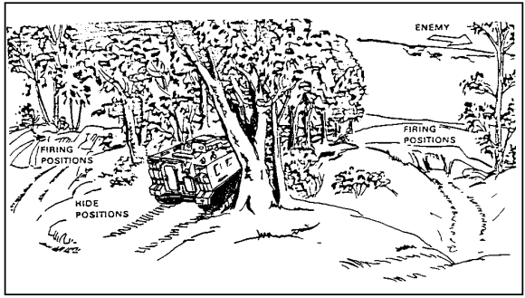
Figure 1-3. Hide Position to Hull-Down Position.
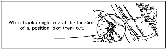
Figure 1-4. Erasing Tracks.
(4) Use the Same Route for All Vehicles. Ensure that all vehicles travel to a position over the same route. This prevents the enemy from knowing how many vehicles are present.
(5) Follow Existing Road and Terrain Features. If at all possible, ensure that the route taken to the position follows existing paths, roads, fences, and natural lines in the terrain.
(6) Exposed Routes. Do not permit exposed routes to end at your position.
(7) Keep Traffic to a Minimum. Keep traffic in and out of the position to a minimum by allowing only essential movements.
5. Guidelines for Employing Natural Camouflage.
Use the following guidelines to employ natural camouflage.
a. Change Natural Vegetation. Ensure that natural vegetation used for camouflage is changed often so that it remains fresh. Wilted vegetation will make your position easy to find.
b. Obtain Camouflage Vegetation from Another Area. Ensure that vegetation used as camouflage is obtained from a different area than your position.
c. Avoid Over-camouflage. Never over-camouflage your position. Ensure that the camouflage matches the environment in which your position is located.
d. Do Not Let Camouflage Interfere with Weapon Fire. Do not allow the camouflage of your position to interfere with the firing of your weapon.
6. Employ Camouflage Nets.
Use the following guidelines to employ camouflage nets.
a. Blend Nets with Surrounding Terrain and Vegetation. When using camouflage nets, ensure that the nets blend with the surrounding terrain or vegetation.
b. Do Not Let Nets Interfere with Weapon Fire. As with natural materials, ensure that nets are emplaced so that they will not interfere with firing from the position. Use the following procedures to emplace nets:
- When using nets with vehicles, ensure that the nets are raised above the top of the vehicle.
- To keep the nets above the vehicles, use poles or small tree branches for support.
- When a camouflage net is used with a hull-defilade position, ensure that the vehicle outline is broken up and that the net drapes over the vehicle and blends with the surrounding terrain, as shown in Figure 1-5.
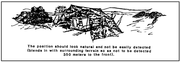
Figure 1-5. Blending Nets with Surrounding Terrain.
- In the event that a hull-down position is not available, use a hide position, as shown in Figure 1-6.
- If the terrain is such that neither a hull-down nor a hide position is available, make the best of existing terrain to conceal the TOW.
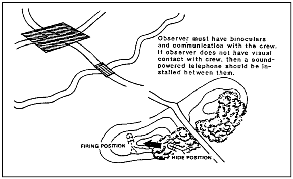
Figure 1-6. Hide Position.
7. Inspect Camouflage.
Use the following procedures to inspect camouflage.
a. Check the Ground Behind the TOW. Ensure that the ground behind the TOW (about 25 meters) is free of leaves and dirt so that the backblast from the weapon does not leave a signature.
b. Avoid Evidence of Digging. Do not leave any evidence of digging. Do not leave equipment lying around. Everything must be concealed or camouflaged.
c. Check the Front of the Position. If possible, move to the front of your position (ground, 35 meters; vehicle, 350 meters) and study your position. Ensure that the position looks natural and blends with its surroundings.
PART B - SUPERVISE THE CONSTRUCTION AND CAMOUFLAGE OF A TOW DISMOUNTED FIGHTING POSITION
1. Dismounted Position.
The dismounted position must protect squads from direct and indirect fires through cover and concealment. The dismounted position is usually dug in with overhead protection, is intended to be retained, and is quite large. Overhead cover must allow the bridge clamp to be raised and the indexing lugs on the encased missile to be inserted into the launch tube indexing slots. As a result, use overhead cover only when it can be properly camouflaged and concealed. Also, position the organic machine gun for self-defense.
When constructing a dismounted position, the squad keeps the TOW system mounted in its vehicle and prepares a range card until the position can support and protect its employment. Only the tripod is used to outline the dismounted position, as shown in Figure 1-7.
Dig the weapon's position first and add overhead protection for the crew and missiles as time allows. Dig a position at least 24 inches deep, as shown in Figure 1-8.
The TOW launcher can easily be detected, especially during daytime. To reduce the possibility of detection, keep the launcher below ground level until it is needed. To accomplish this, release the friction lock on the rear leg and slide the leg back into the notch at the rear of the position. Avoid getting any dirt or debris into the launch tube.
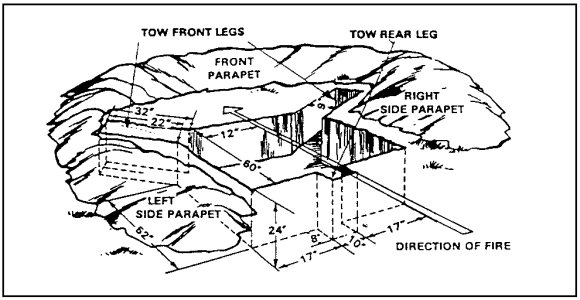
Figure 1-7. Outline of the Dismounted Position.
2. Construct the Position.
Use the following procedures to construct the dismounted position (Figure 1-8).
a. Build a Parapet. Build a parapet to the front and the flanks of the position. To provide protection from small-arms fire and fragments from mortar and artillery rounds, the parapet should be covered by at least 18 inches of dirt. To ensure that missiles do not hit the ground before reaching a target, leave at least nine inches of clearance under the muzzle of the launch tube (that is, between the bottom of the launch tube and the parapet). Do not place dirt or equipment in the backblast area. Scoop out a place between the tripod legs for the missile guidance set (MGS), either to the front or under the tripod, as shown in Figure 1-8. To ensure that missiles do not hit the ground before reaching a target, ensure that there is adequate line-of-sight clearance (at least 30 inches) from 500 to 900 meters in flat terrain and that the position is not more than 24 inches deep.
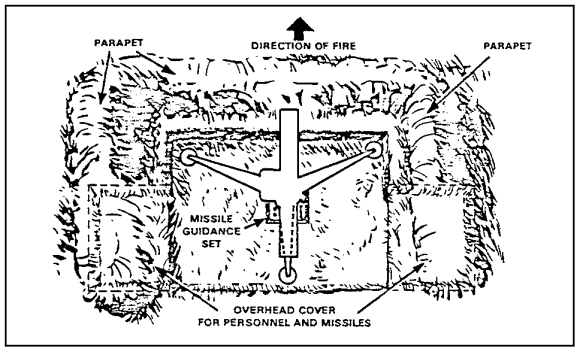
Figure 1-8. Position of the Missile Guidance Set.
b. Provide Overhead Protection. Provide overhead protection for squad personnel and missiles by digging squad positions on each side and to the rear of the position, as shown in Figure 1-9. Build the overhead cover at ground level to make the position more difficult to detect. Logs that are four to six inches in diameter, covered by 12 to 14 inches of dirt, provide adequate protection against mortar or artillery fragments.
c. Improve the Position and Keep It Dry. To keep the position dry, lay a layer of packing material (sandbags, for example) or waterproof material (canvas, plastic, or a poncho) over the logs before adding the dirt.
d. Improve the Position. Improve the position by adding overhead cover for the crew and the missiles. Dig to the flank (90 degrees to the primary section of fire). Use the strongest material available for the roof. Put sandbags, plastic, or canvas down before throwing the dirt on the roof to keep the ceiling from leaking.
Place at least 20 inches of dirt on top of the storage/protective area, as shown in Figure 1-10.
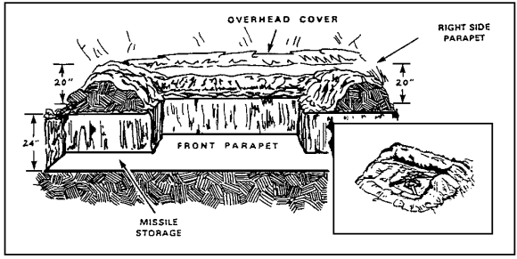
Figure 1-9. Overhead Cover.
e. Disconnect the Missile Guidance Set. Disconnect the missile guidance set and position it in the place made for it. Then place the launcher into the position. Reconnect the missile guidance set and check the boresight.
3. Camouflage the Position.
Use the following procedures to camouflage the position.
a. Place Sod on the Parapet. Place sod from the position on the parapet so that it looks natural and has a good chance of growing.
b. Cover Fresh Dirt. Cover all fresh dirt with leaves or brush so that it blends with the ground around the position.
c. Use Vegetation If Required. If additional vegetation must be used to break up the outline of the parapet, get it from far to the rear of the position. It should look like the vegetation around the position and, if possible, should have intact roots. Do not use so much vegetation that the position has more than the surrounding area. Camouflage the holes or cuts from which the vegetation was removed.
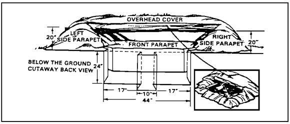
Figure 1-10. Storage/Protective Area.
d. Camouflage the Position. If the position is covered, camouflage it as you did the parapet. If it is not covered, camouflage the position using camouflage nets or available brush, branches, etc., so that it is not visible from above.
e. Replace Foliage. Replace foliage if it withers or begins to change color. Attempt to get sod and vegetation that is used as camouflage to grow so that the position will improve as time passes. Remember that the position can always be improved.
f. Approach the Position from the Rear. Approach the position from the rear, ensuring that you leave no trace of your passing. Especially, cover all footprints around and leading into and out of the position.
g. Avoid Littering. Do not litter the area or make unnecessary noise while constructing or camouflaging the position.
h. Avoid Disturbing Vegetation. Do not disturb vegetation that is not used in constructing or camouflaging the position. The area around the position should look as natural as possible.
4. Inspect the Camouflage.
You inspect the camouflage using the same procedures as for the mounted TOW, found in paragraph 7 of Part A of Lesson One of this subcourse.
5. Hunter-Killer Position.
To conduct a hit-and-run anti-armor ambush, a small position may be created that is just large enough to conceal the system and the crew until the ambush is executed. These positions use no overhead cover and normally take advantage of existing terrain features such as folds in the ground.
6. Urban Terrain Position.
When anti-armor units are employed in urban terrain, the same considerations for position selection apply.
a. Positioning the TOW in a Building. Other considerations apply if the TOW is positioned in a building. You fire the TOW from a building only when the following conditions exist:
- The building is sturdy.
- The ceiling is at least two meters (seven feet) high.
- The room is at least five meters by eight meters (17 feet by 24 feet) or larger.
- There are two square meters (20 square feet) of ventilation to the rear of the system (an open door two meters by one meter (seven feet by three feet) provides that much ventilation).
- Glass is removed from all windows and doors, the floor is swept, and furniture and other objects that could be blown around are removed from the room.
- Everyone in the room is wearing earplugs and ballistic eye protection and is positioned forward of the rear end of the launch tube.
b. TOW Firing Limitations in Urban Terrain. Urban terrain affords the TOW squad improved conditions to maximize cover and concealment. However, you must consider firing limitations. Two clearance requirements ensure that a missile will not hit the ground before reaching a target:
- There should be at least nine inches of muzzle clearance around the end of the launch tube. This ensures that the wings and the control surfaces do not hit anything when they extend after the missile clears the launch tube. If the wings are damaged or if they catch on an object, the missile will fly erratically or go to the ground.
- There should be at least 30 inches of clearance between a gunner's line of sight to a target and any obstruction that is between 500 and 900 meters from the firing position, as shown in Figure 1-11.
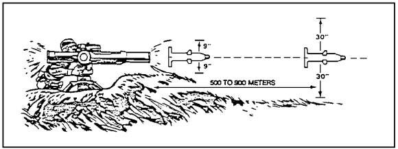
Figure 1-11. Clearance Requirements.
If line-of-sight clearance is less than 30 inches, the probability of the missile's hitting the ground or an obstruction is increased. Figure 1-12 shows the probability of survival for the TOW. A missile does not precisely follow a gunner's line-of-sight to the target.
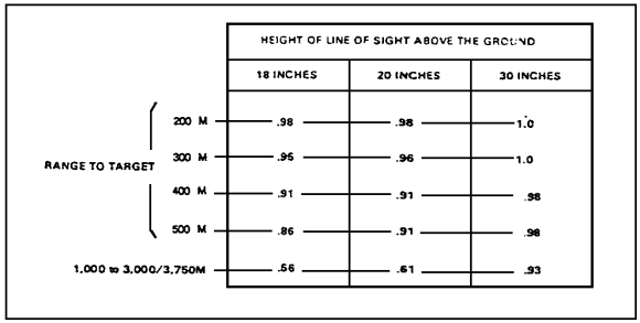
Figure 1-12. Probability of Survival for the TOW.
7. Kneel the Launcher.
Use the following procedures to lower (kneel) and raise the launcher.
a. Lower the Launcher Below Ground Level. If the gunner is being suppressed by fire and must further conceal the TOW, he can kneel (lower) the launcher below ground level. To kneel the launcher, follow these steps:
- Have the gunner lift the encased missile with his right shoulder.
- Release the friction locking handle and the detent stop on the rear leg and allow the rear leg to slide back into its notch. The launcher will move back by its own weight.
- Depress and lock the launch tube in the full DOWN position so that it does not stick above the frontal protection.
b. Raise the Launcher. To raise the launcher, follow these steps:
- Lift the rear of the encased missile and push forward and down on the rear leg. (The elevation and the azimuth locks must be engaged).
- Check the level indicators and the friction locking handle.
PART C - PLAN AND CONTROL TOW SECTION FIRES
1. Fire Planning.
Fire planning is an integral part of the troop-leading procedure. This planning starts as soon as a leader receives a mission and continues until the mission is accomplished. The goal of fire planning is to determine how platoon leaders should distribute and control the fires of their platoons to best support an operation. Fire planning also includes indirect fire. However, this paragraph discusses direct fire only.
a. Assignment of Sectors. The platoon leader assigns the general positions to his sections to cover the assigned sector of fire. He uses easily identifiable terrain features to define the limits of each sector. The TOW section leader selects the precise weapon positions and continues the fire planning process by drawing a sector sketch.
(1) Prepare a Sector Sketch. Each section leader prepares two copies of a sector sketch to help him coordinate the fires of his squads, as shown in Figure 1-13. The section leader's sector sketch includes the section's primary, alternate, and supplementary positions. He keeps one sketch and gives the other to his platoon leader. The sector sketch shows the following:
- The main terrain features in the sector of fire and the ranges to them.
- The squad's primary and secondary sectors of fire.
- The maximum engagement lines.
- The engagement areas.
- The target reference points (TRPs).
- All dead space.
- The phase lines where firing should begin or where the squad is to disengage.
- Obstacles and indirect-fire targets.
(2) Ensure that TOWs are Sited Correctly. The platoon leader checks the weapon positions to ensure that the TOW systems are sited correctly. If possible, he walks around the position and checks it from the enemy's perspective. Then he uses the section sector sketches to make a platoon sketch, as shown in Figure 1-14. He makes two sketches. He keeps one and gives the other to his company commander. The platoon leader also uses the section sector sketches to develop an engagement matrix, as shown in Figure 1-15. This matrix shows what engagement areas can be covered by each section and from each position.
b. Defensive Fire Planning. To develop a defensive fire plan, the Anti-armor leader uses the following procedures:
- Assigns to each subordinate unit either a primary and a secondary sector of fire or an engagement area, a primary position, and one or more alternate positions.
- Designates targets and additional fire control measures, such as TRPs, phase lines, or target priorities, to coordinate fire when more than one section is firing into the same engagement area or sector.
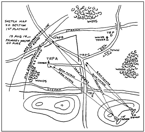
Figure 1-13. Section Sector Sketch.
- Integrates target information from subordinate leaders (normally provided on section sector sketches, individual squad range cards, or both). He then reviews this target information to ensure that fire is properly distributed across his sector and that sufficient control measures have been established.

Figure 1-14. Platoon Sector Sketch.
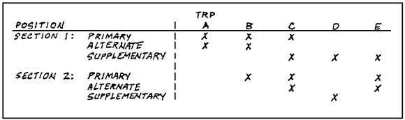
Figure 1-15. Platoon Engagement Matrix.
- Coordinates and integrates his TOW fires with those of tanks, other Anti-armor weapons, and indirect fire.
- Completes the fire plan and gives a copy of the sector sketch to the control headquarters or to the supported unit commander--for example, to the Anti-armor company commander or the task force commander--and to the mortar platoon leader and the fire support team (FIST).
c. Offensive Fire Planning. Offensive fire planning relies more on fire patterns and standing operating procedures (SOPs) to bring effective fire onto the enemy than does defensive fire planning. This is often true during a movement to contact when knowledge of the enemy is vague or when the terrain is unknown. To compensate for not knowing the terrain, the platoon leader can use a thorough map reconnaissance along with a study of terrain information from the battalion Operations and Training Officer (S3). The platoon leader uses this information and the commander's scheme of maneuver to perform the following actions:
- Select positions where his sections can overwatch the forward movement of or can provide support-by-fire for the supported unit.
- Ensure that TOW fires are integrated with other overwatching fires. This can be done using TRPs, phase lines, priorities of engagement, and sectors of fire in the same way as in defensive fire planning.
- Plan how targets will be designated for TOW engagement. This can be done with colored smoke, signal panels, or other means.
- Identify areas in which TOW overwatch is not possible and to advise the commander of this so that other weapons can be assigned to this task.
- Identify routes between positions along the axis of advance or in the zone of action that allow rapid movement and that provide security for the moving anti-armor sections.
- Complete the plan with the approval of the supported commander and to brief subordinate leaders.
2. Fire Control and Distribution.
Fire control measures are usually established by the platoon leader or the company commander. They are designed to take advantage of the TOW's range, accuracy, and destructive power by distributing TOW fires equally across the battle area. Effective fire control and distribution measures accomplish the following:
- Prevents firing more than one missile at the same target.
- Avoids revealing TOW locations.
- Ensures complete coverage of all armor avenues of approach.
- Enables TOWs to fire first.
- Provides for the destruction of the most important targets first.
- Gains the best shot at a target.
- Affords the leader the ability to better control TOW fires.
The success of anti-armor platoons in combat depends upon how quickly and effectively platoons engage targets. All TOW fires must be controlled to ensure the full coverage of the target area and to prevent the multiple engagement of a single target. This paragraph discusses some standard techniques for platoon and section leaders to control and distribute fires in combat.
Fire control and distribution measures must be simple. Leaders must know them well. Leaders must use these measures routinely, with no need for detailed instructions. The following are the commonly used measures for controlling the fires of an anti-armor platoon.
a. Priority of Engagement and Sectors of Fire. Fire control measures are of two types: priority of engagement and sectors of fire.
(1) Priority of Engagement. Targets in battlefield formations vary. They can be tanks, BMPs, BRDMs, BTRs, or air defense vehicles. TOW fires can be distributed rapidly and controlled effectively if a priority of engagement is assigned to all the sections or if each section is assigned a specific type vehicle to engage initially. For example, one section can engage tanks while another engages command vehicles and BMPs. This method works best during offensive or retrograde operations when surprise targets may appear, allowing little time for detailed instructions. Regardless of engagement priorities, a target presenting a threat to a unit must be engaged immediately. Sometimes, a priority of engagement by type of vehicle may be assigned. For example, if enemy air defense weapons are preventing the Air Force or attack helicopters from operating in the forward battle area, the destruction of enemy air defense weapons may be given a priority. If enemy carrier-mounted antitank guided missiles are reducing the effective employment of tanks, they may be designated as priority targets. When a target is assigned an engagement priority, it is engaged first when it appears. Other targets are engaged after the priority target has been destroyed. The priority of engagement can be used as a failsafe measure if radio communication is lost or jammed.
Engagement priorities can prevent multiple engagements of one target when:
- Sectors of fire have not been assigned.
- Overlapping sectors of fire have been assigned.
- More than one section is covering a main avenue of approach.
| NOTE: | In the absence of assigned engagement priorities, you should establish priorities to destroy first those targets that are the greatest threat to the accomplishment of your mission and targets which, when destroyed, will break up the momentum of the enemy's attack by destroying his command and control element. |
(a) Use of Code Words to Change Engagement Priorities. Code words may be used to change engagement priorities. For example, a code word can be used to shift priority from tanks to air defense vehicles when the latter threatens friendly air operations. Engagement priorities are also useful when neither sectors of fire nor overlapping sectors of fire have been assigned. Like phase lines, engagement priorities are useful if communications are lost.
(b) Emerqency Signals. Effective fire control depends upon good communications. Radio is the main means that commanders and leaders have to control their TOW assets. However, mainly in a nuclear or electronic warfare (EW) environment, radio communication can be lost. Emergency signals are used to control the fires of squads and sections, and wire also can be used. Alternate signals must be known. Orders must be issued so that personnel know how to continue the battle if initial communications are lost. Sometimes, pyrotechnics are the only method available to control fires. Their use must follow the signal operation instructions (SOI) and must be practiced often. Examples of simple signals that the SOI may specify are as follows:
Signal |
Meaning |
| Red star cluster Green star cluster White star cluster Red and white combination |
Stop firing Start firing Switch to secondary sector Switch to alternate sector |
(c) Fire Commands. Because speed and accuracy are vital in target engagement, fire commands must be clear and concise. In the stress of battle, a platoon leader or a section leader must be able to analyze a situation quickly and to follow up with concise, understandable, and complete fire commands.
The use of a standard fire command ensures that the correct target is engaged rapidly. It also minimizes radio transmission time. Fire commands should be short. The following fire elements of the standard fire command should be used.
* When the section leader is calling a fire mission to your squad over wire or radio, the establishment of communications is a sufficient alert.
** Only the elements which change from the previous fire command are announced in this command. However, "CEASE TRACKING" or "CEASE TRACKING, OUT OF ACTION" is always announced in the subsequent fire command.
(d) Format. A standard format for fire commands ensures that all needed information is given quickly. Omitting the control element when it is not needed shortens the fire command. Also, the description may be omitted when target priorities have been assigned--for example, when the targets are tanks, the fire command specifies otherwise. This omission simplifies the command if tanks and BMPs appear at the same time, but the platoon or the section has been directed to engage tanks only. In sequence, the elements of a fire command are as follows:
Element |
Example |
| Alert | TANGO FOUR ONE, THIS IS TANGO FOUR ZERO, ENGAGEMENT CONDITION: YELLOW/WHITE |
| Missile Type | TOW 2 ALPHA |
| Description | FOUR TANKS AND THREE BPMs |
| Location | EAST OF TRP ZERO ZERO FOUR |
| Control (option) | DEPTH |
| Execution | FIRE AT MY COMMAND |
| Closing | CEASE FIRE |
(e) Elements. The platoon leader normally gives the fire command to the section leaders. Because each squad is in the platoon radio net, the section leaders rarely need to repeat the entire fire command to the other squads in their sections. If more instructions are needed, only the elements of the fire command that change are given. Once the platoon leader completes a fire command, each section leader acknowledges it in turn. The second squad in each section should then acknowledge so that each section leader knows that both squads have received and understood the command. The following sample SOI extract identifies the elements involved in the sample fire commands.
Sample SOI Extract |
Call Sign |
| Platoon | C5T |
| Platoon leader | C5T40 |
| 1st Squad (1st section leader) | C5T41 |
| 2d Squad | C5T42 |
| 3d Squad (2d section leader) | C5T43 |
| 4th Squad | C5T44 |
| Platoon sergeant | C5T45 |
EXAMPLE 1: This is the platoon leader's fire command for both sections of the platoon to engage assaulting tanks.
TANGO (entire platoon), THIS IS TANGO FOUR ZERO
TEN TANKS
DIRECT FRONT
CROSS
FIRE
EXAMPLE 2: This is the platoon leader's fire command to engage assaulting BMPs and tanks. The platoon leader alerts the entire platoon and indicates that he wants both sections to fire. He then specifies that Section 1 will engage the BMPs (TANGO FOUR ONE, BMPs) and that Section 2 will engage the tanks (TANGO FOUR THREE, TANKS). Because the platoon leader leaves out the control element, each section leader adds it by telling the other squad, "Depth, cross," if needed for control within the section.
FRONTAL FIRE is understood unless the section leader specifies otherwise.
TANGO, THIS IS TANGO FOUR ZERO
BMPs AND TANKS
WEST OF TRP ZERO ZERO SEVEN
TANGO FOUR ONE, BMPs
TANGO FOUR THREE, TANKS
FIRE
EXAMPLE 3: This is the platoon leader's command to continue the engagement after the BMPs are destroyed. The platoon leader instructs Section 1 to shift fire to the tanks and to continue to engage. Because the control element is omitted, FRONTAL FIRE is understood. Although the command does not mention Section 2, that section continues to fire, based on his last instructions.
TANGO FOUR ONE, THIS IS TANGO FOUR ZERO
TANKS
EXAMPLE 4: This is the platoon leader's command to stop the engagement.
TANGO, THIS IS TANGO FOUR ZERO
CEASE FIRE
b. Sectors of Fire and Engagement Areas. Sectors of fire and engagement areas are specific areas to be covered. They are assigned to each squad, section, and platoon. They clearly identify the part of the battlefield that must be covered by observation and fire. In most situations, the terrain and the number and the type of weapons available to cover an area dictate how sectors of fire or engagement areas are assigned.
(1) Sector of Fire. A sectors of fire is the area that a TOW squad is assigned to cover. Sectors are assigned to ensure that fires are distributed throughout the battle area; that all armor avenues of approach are covered; and to facilitate the massing of fires. Sectors of fire are usually fan-shaped, but they can be any shape, as shown in Figure 1-16.
A sector of fire (as shown in Figure 1-17) is designated by its left and right limits. The limits of the sector can be defined by easily recognizable terrain features, such as roads, streams, hills, or wood lines. Sectors of fire usually extend from firing positions to the maximum engagement range of the TOW. They should be assigned so that each is fully covered with the correct type of fire. Also, mutual support is maintained between sections. Mutual support can be improved by assigning primary and secondary sectors of fire, as shown in Figure 1-18. That is, to improve mutual support, one section's secondary sector of fire should correspond to another section's primary sector of fire. When no targets are in the primary sector, fire is shifted to the secondary sector upon order. It also can be shifted to cover another TOW section if that section must be moved to an alternate position.
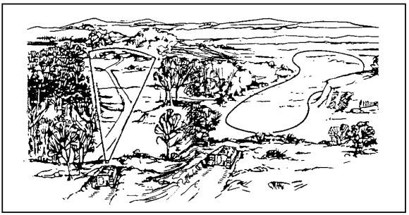
Figure 1-16. Sectors of Fire.
(a) Secondary Sector of Fire. A TOW squad is assigned a secondary sector of fire along with its primary sector of fire. When the terrain permits, the primary sector of one squad is the secondary sector of another. This provides mutual support between squads and permits the massing of fires in either sector, as shown in Figure 1-18.
(b) Overlapping Sectors of Fire. A TOW squad may be assigned a sector of fire that overlaps another squad's sector, as shown in Figure 1-19. This is done to concentrate TOW fires in a critical area and to gain a flanking shot. The platoon leader or the company commander coordinates the two squads' fires or designates the leader in the more favorable position as responsible for fire coordination in the sector.
(c) Report Sectors of Fire That Cannot Be Covered. If your squad is assigned a sector that it cannot cover, report it immediately to your leader or commander.
(2) Engagement Area. An engagement area is an area alongside a mounted enemy avenue of approach that is defined by the terrain around it, as shown in Figure 1-20. This surrounding terrain must be easily identifiable. It must be located in such a way that the fires of multiple friendly forces can be concentrated onto it. Engagement areas may be used at platoon, company, and battalion level. Other measures, such as TRPs and phase lines, should be used along with engagement areas to further control and distribute fires.
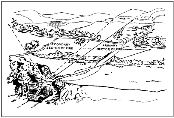
Figure 1-17. Primary and Secondary Sectors of Fire.
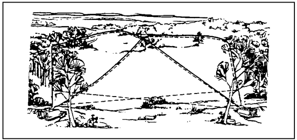
Figure 1-18. Secondary Sector of Fire.
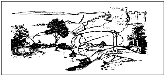
Figure 1-19. Overlapping Sectors of Fire.
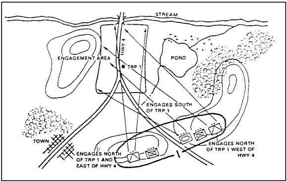
Figure 1-20. Engagement Area.
For example, if a mounted enemy avenue of approach is narrow or if the fire of an entire platoon is needed in a critical area, such as a choke point, sectors of fire can overlap. Because this increases the problem of control and the probability of target overkill, other control measures (engagement priorities, fire patterns, TRPs) are also needed. When sectors of fire overlap, leaders must select positions where they can observe and coordinate fires.
c. Target Reference Point. A TRP is a prominent natural or man-made terrain feature, such as a road intersection, hill, or bridge, designated by the commander, leader, or gunner to allow the rapid identification of targets and to control direct fires. A TRP is a reference point (RP) for designating targets, for shifting fire, or for assigning sectors of fire. They are recorded on range cards for easy reference, as shown in Figure 1-21.
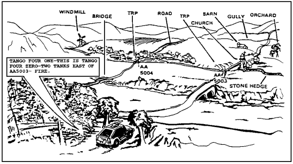
Figure 1-21. Use of Target Reference Points.
| NOTE: | The direction from TRPs is given in cardinal directions (north, south, etc.) rather than as left or right. However, when you are giving fire commands to your squad and are in the same location as the squad, you can use left or right ease of understanding and rapid target engagement. |
(1) In Defense. In the defense, TRPs are located along mounted avenues of approach where the enemy is likely to be and on prominent terrain features. To avoid confusion, TRP should be limited to the number required to distribute and control fire. TRPs may be used to control both direct and indirect fires. When a TRP is used to designate targets, as shown in Figure 1-22, directions are given by the compass rather than by right or left because each squad may be facing the TRP from a different direction.
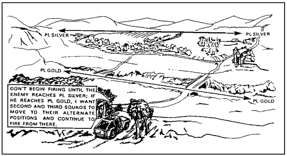
Figure 1-22. Use of Phase Lines to Control Fires.
(2) Numberinq TRPs. TRPs are numbered sequentially, using three-digit numbers. However, the numbers are not chosen at random. When a TRP is recommended and accepted as an indirect fire target, it is given a number from an assigned block of target identification numbers. A target identification number has two letters and four numbers--for example, AB 5010. When applicable, the identification numbers are recorded on range cards and sector sketches for easy reference and coordination. To simply fire commands in a direct-fire engagement, targets may be referred to by the last three digits. For example, target AB 5010 may be referred to as TRP 010.
d. Phase Lines. A phase line is a linear control measure normally used to control movement. It is also used to control and distribute the fire of several widely separated anti-armor squads or platoons.
(1) Use of Terrain Features to Desiqnate Phase Lines. Any prominent or man-made linear terrain feature, such as a ridge line, road, railroad tracks, river, or stream, may be used to designate a phase line. In either offensive or defensive operations, crossing a phase line can be the signal to start or stop firing, to shift fire to another sector, or to indicate when squads, sections, or platoons should move to alternate or supplementary positions. Figure 1-22 shows a platoon leader using phase lines to cue his squads to fire and displace to an alternate position.
(2) Use of Phase Lines to Specify Tarqet Priorities. Phase lines can also be used to specify when target priorities are to change. For example, the platoon leader might say, "I want both sections to engage only tanks when the enemy reaches PL Silver. Then I want Section 1 to begin engaging BMPs and any command vehicles identified." In addition to being a simple and effective control measure, a phase line can be assigned as an emergency control measure when radio communication is interrupted. Section leaders know that if an enemy reaches a designated phase line, they are to follow their orders without further communication.
3. Fire Patterns.
Fire patterns are standard techniques for distributing tank and anti-armor fires upon multiple targets. Basically, have each TOW squad start at opposite ends of a formation and work toward the center to prevent multiple engagements of one target. They are most often used when terrain-oriented fire control measures, such as TRPs or engagement areas, have been identified. When used, fire patterns are announced as part of the section fire command. The three basic fire patterns are frontal, cross, and depth.
a. Frontal Fire. Frontal fire (shown in Figure 1-23) is most effective when targets are dispersed or are moving laterally across a sector of fire. In employing frontal fire, flank squads engage flank targets first. As targets are destroyed, fire is shifted toward the center of the formation. Frontal fire is least effective when target vehicles are moving toward the firing positions. When this happens, the target vehicles' observation and firepower are oriented toward the platoon. Therefore, friendly squads must fire into the frontal (thickest) armor on the target vehicle.
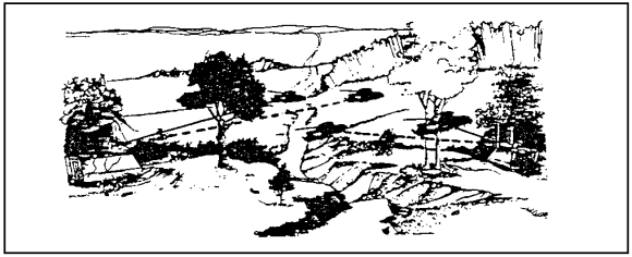
Figure 1-23. Frontal Fire.
b. Cross Fire. Cross fire (shown in Figure 1-24) is most effective when targets are dispersed laterally but are moving toward the firing positions. It is used for flank shots and for avoiding detection when the target is moving toward firing positions. Each squad engages a target on the opposite flank. As targets are destroyed, squads shift fire toward the center of the formation.
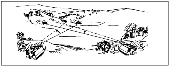
Figure 1-24. Cross Fire.
c. Depth Fire. Depth fire (shown in Figure 1-25) is most effective when targets are exposed in depth. One squad or section engages the nearest targets while the other engages the farthest targets. Then they shift fire toward the center of the formation. If the unit SOP does not specify which squad or section engages near targets and which engages far targets, then the determination of which squad or section fires at what target is made by the leader who is responsible for controlling the fires.
d. Changes to Fire Patterns. Fire patterns are changed as needed. After being engaged, the enemy will change his formation or direction of movement, which requires a corresponding change to fire patterns. Enemy vehicles avoid moving in easily recognizable formations. Also, enemy formations appear as a mass of vehicles due to uneven terrain and point of view. The fire pattern that is selected should be based upon how the formation appears relative to the firing position and the leader's estimate of how best to engage the enemy.
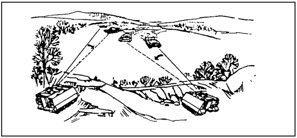
Figure 1-25. Depth Fire.
PART D - INSPECT AN ANTIARMOR RANGE CARD
1. Range Card.
A range card is a sketch or a diagram of the terrain that a weapon must cover by fire. It shows possible target areas and terrain features plotted relative to a firing position. The information on a range card is used to plan and control fire, to rapidly detect and engage targets, and to orient replacement personnel and units.
2. Inspect the Range Card.
Ensure that each gunner performs the following actions:
a. When Enemy Contact Is Possible. When enemy contact is possible, prepare one range card for each primary, alternate, and supplementary squad position. Also, prepare one-for any static squad position such as in an assembly area.
b. Prepare Copies of the Range Card. Prepare a range card as soon as possible after moving into a firing position. Prepare two copies of each range card. Retain one copy of each range card with the squad and give the other to the section leader. The section leader uses his copy to prepare a section sector sketch. Standard printed range card forms are best to use. If no forms are available, use anything available to write on.
c. Indicate the Left and Right Limits. Draw the weapon symbol in the center of the small circle. Draw two lines from the TOW position. The lines should extend left and right to show the limits of the sector. These lines are the vehicle's left and right limits. Place a circled "L" and "R" at the end of the appropriate limit lines, as shown in Figure 1-26. Even if a sector is narrow, spread the information out on the range card as much as possible to ensure that all items can be easily shown.
d. Indicate the Increments of Distance. Find the terrain feature farthest from the position that is still known to be within the weapon system's range to determine the value of each circle. Determine the distance to the terrain feature and round off to the next highest hundred. Determine the highest number of circles that will divide evenly into the distance (that is, that will result in a whole number). The result is the value of each circle. Draw the terrain feature on the appropriate circle. Clearly mark the increment for each circle across the area where DATA SECTION is written.
For example, a 3,145-meter hilltop is used in Figure 1-27. (The increments are shown, in meters, below the line above the heading "DATA SECTION) as 4 (for 400), 8 (for 800), 12 (for 1,200), 16 (for 1,600), 20 (for 2,000), 24 (for 2,400), 28 (for 2,800), and 32 (for 3,200)). To find the distance of the hilltop from the position, read to the left or right until you reach the number 32 (for 3,200 meters). Then follow the line up from the number 32 to the right, if you read to the left to locate 32, or to the left, if you read to the right to locate 32. The line will intersect with the symbol for the hilltop, showing it to be located approximately 3,200 meters from the position.

Figure 1-26. Placement of Weapons Symbol and Left and Right Limits.
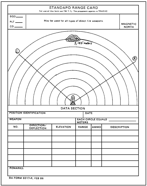
Figure 1-27. Circle Value.
Round the distance to 3,200 meters.
Divide 3,200 meters by eight to equal 400 meters (the value of each circle): 3,200 divided by 8 = 400 meters.
| NOTE: | To find the greatest number of circles that will divide evenly into the distance in meters, start with nine (because there are nine circles on the standard range card). If nine will not divide evenly into the distance, try eight (the next highest number of circles on the standard range card). Continue until you find the greatest number of circles that will divide evenly into the distance. |
(1) Limits. Figure 1-28 shows a farmhouse at 2,000 meters on the left limit. The right limit is noted by the wood line at 2,600 meters. The distance to these features can be determined by using a map or a handheld laser range finder. The circle markings can help in positioning the features on the range card.
(2) TRPs and Reference Points. All the TRPs and reference points (RPs) in the sector should be marked with a circled number, beginning with 1. Figure 1-29 shows the hilltop as RP 1 and two road junctions as RP 2 and RP 3. Sometimes, a TRP and an RP are the same point, as with RP 2 and RP 3. This occurs when a TRP is used for target acquisition and range determination. The TRP is marked with the first designated number in the upper right quadrant. The RP is marked in the lower left quadrant of the cross. Road junctions are drawn in three steps:
- First, the range is determined to the junction.
- Second, the junction is drawn.
- Third, connecting roads from the road junction are shown.
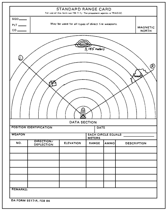
Figure 1-28. Terrain Features for Left and Right Limits.
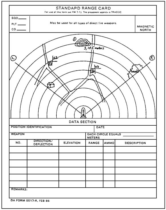
Figure 1-29. Reference Points and Target Reference Points.
(3) Dead Space. Dead space is shown as an irregular circle with diagonal lines drawn inside, as shown in Figure 1-30. The circle and the diagonal lines extend out from any object that prohibits observation or direct-fire coverage to the farthest maximum engagement line. If the area beyond the dead space can be engaged, then the circle is closed. For example, an area of lower elevation will have a closed circle because the area beyond it can be engaged.
(4) Maximum Engagement Lines. Maximum engagement lines are shown in Figure 1-31. They are drawn at the maximum effective engagement ranges of each weapon if dead space does not limit range capabilities. In this figure, the maximum engagement line for the MK 19 extends beyond the dead space. This indicates a higher elevation beyond the dead space where area suppression is possible. Maximum engagement lines are not drawn through dead space. The maximum effective ranges for weapon systems used on the HMMWV interchangeable mount systems are as follows:
| M2 (.50-caliber) | 1,800 meters (tracer burnout) machine gun |
| M60 machine gun | 900 meters (tracer burnout) |
| MR 19 machine gun | 2,200 meters (impact) |
| TOW 2 | 3,750 meters (impact) |
(5) Weapon Reference Point. The weapon RP shown in Figure 1-32 appears as a line with a series of arrows. The line extends from a known terrain feature and points in the direction of the TOW symbol. The weapon RP is numbered last and is given a six-digit grid. When no terrain feature is available to designate as the weapon RP, the vehicle's location is shown in the "Remarks" block of the range card as an eight-digit grid coordinate. (In Figure 1-32, the weapon RP is 4).
| NOTE: | When the weapon RP cannot be drawn precisely on the sketch due to the vehicle's location, it is drawn to the left or the right, nearest the actual direction. |
e. Data Section. Complete the data section of the range card (Figure 1-33).
(1) Position Identification. Either the primary, the alternate, or the supplementary position should be noted. Alternate and supplementary positions must be clearly identified.
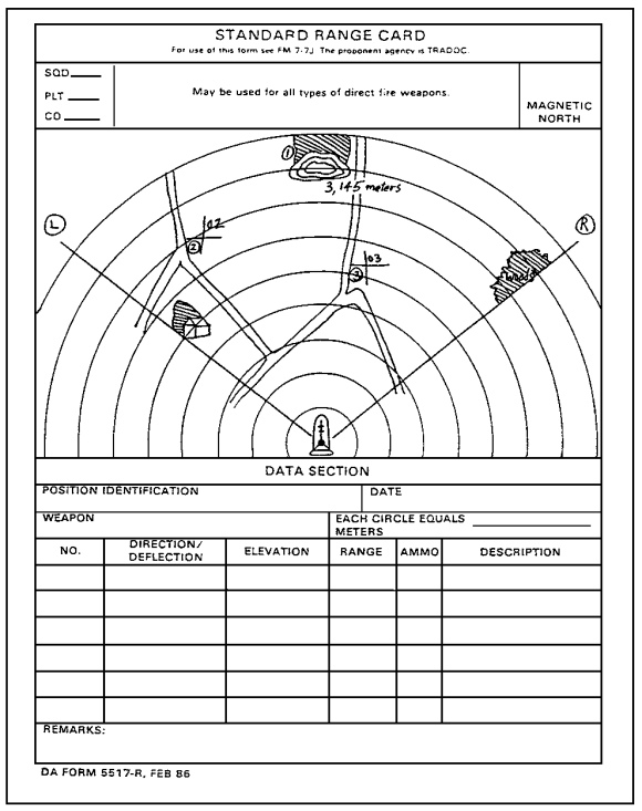
Figure 1-30. Dead Space.
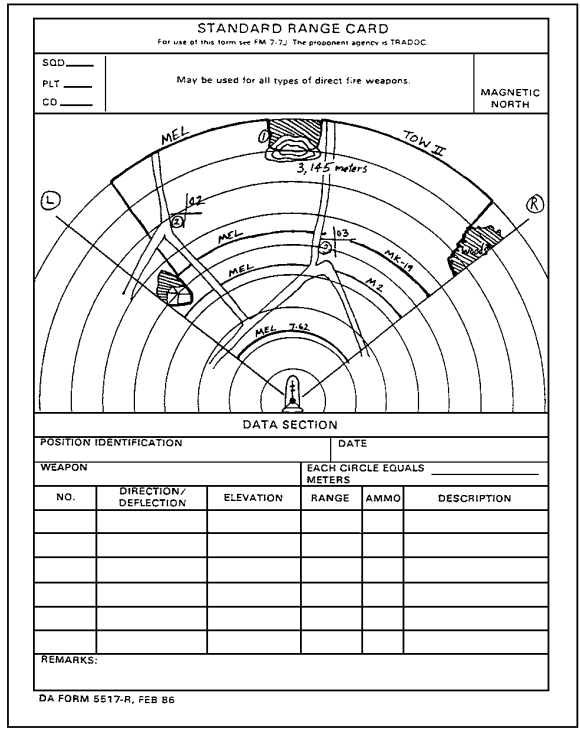
Figure 1-31. Maximum Engagement Lines.
Figure 1-32. Weapon Reference Point.

Figure 1-33. Example of a Completed Range Card.
(2) Date. The date and the time that the range card was completed should be noted. Range cards are like fighting positions. They are constantly being updated. The date and the time help commanders determine what data are current.
(3) Weapon. In the weapon block, the type of the TOW-mounted vehicle and the vehicle bumper number should be noted.
(4) Distance (in Meters). Each circle equals a particular number of meters (to be determined). The distance between the circles should be entered in meters.
(5) Number (NO.). Starting with the left and the right limits, TRPs and reference points (RPs) should be listed in numerical order.
| NOTE: | Based upon SOP and mission, enemy, terrain, troops, and time available (METT-T) factors, leaders from the light, airborne, or air assault antiarmor platoons may designate a type of target (vehicle) to be dedicated to TOWs, MK 19s, or .50-caliber machine guns. |
(6) Direction/Deflection. The direction (in degrees) is read from a lensatic compass. In the M966 HMMWV, the most accurate technique is for the gunner to aim at the terrain feature while the driver dismounts, aligns himself with the launch tube and terrain feature, and measures the azimuth. Within the Improved TOW Vehicle (ITV), the gunner can use the turret azimuth indicator to measure the azimuth to the target.
(7) Elevation. The TOW system has no elevation indicator but can elevate to 30 degrees above and 20 degrees below the horizontal plane.
(8) Range. The range (distance) in meters from the vehicle position to the left and right limits, TRPs, and reference points (RPs) should be noted.
(a) Ammunition. The types of ammunition used should be noted.
(b) Description. The name of the object--for example, farmhouse, wood line, hilltop--should be noted.
(c) Remarks. The weapon RP data should be entered. These data include at least the following:
- A description of the type of weapon RP.
- The magnetic azimuth.
- A six-digit or an eight-digit grid coordinate for the weapon.
- The distance from the weapon RP to the vehicle position.
f. Marginal Information. Complete the marginal information at the top of the card.
(1) Unit Description. This refers to squad, platoon, and company. Units to the company level should be included.
(2) Magnetic North. The range card should be oriented with the terrain and the direction of the magnetic north arrow.
3. Stake the Position.
After a range card has been completed, ensure that the actual firing position is marked with ground stakes. This enables either the original or the relief squad to occupy the firing position and to use the data from the range card for the position. Three stakes are needed to mark the position, as shown in Figure 1-34.
a. Placing the Stakes. One stake is placed in front of and centered on the vehicle. It should be long enough that the driver can see it while he moves the vehicle into position. The other two stakes are placed parallel to the left side of the vehicle and is lined up with the hubs on the front and the rear wheels. The stakes are placed close to the vehicle with enough clearance to allow a driver to move into the position without knocking them down. The stakes are driven firmly into the ground. Engineer tape, luminous tape, or chemical lights can be placed on the friendly side of the stakes to make them easier to see during limited visibility.
b. Reoccupying a Position. To reoccupy a position, the driver aligns his vehicle on the front stake and moves forward slowly until the two stakes on the left of his vehicle are centered on the front and rear hubs. Units equipped with Improved TOW Vehicles (ITVs) use the azimuth indicator on the ITV for positioning stakes and reoccupying positions (see FM 23-34).
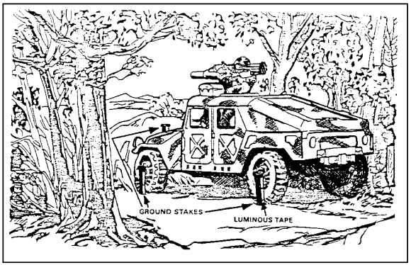
Figure 1-34. Staking the Position.
Practice Exercise