|
RDL Homepage |
Table of Contents |
Document Information |
Download Instructions |
LESSON 1
EMPLOY THE HORNET
OVERVIEW
LESSON DESCRIPTION:
In this lesson, you will learn to employ the Hornet in four tactical scenarios. The scenarios are—conventional minefield reinforcement, scatterable minefield reinforcement, area-disruption obstacle, and gauntlet obstacle.
TERMINAL LEARNING OBJECTIVE:
| ACTION: | You will learn to employ the Hornet. |
| CONDITION: | You will be given a mission scenario and the material contained in this lesson. |
| STANDARD: | You must demonstrate your knowledge of how to perform premission requirements and install and arm the Hornet. |
| REFERENCE: | The material contained in this lesson was derived from FM 20-32. |
INTRODUCTION
In this lesson you will learn how to perform all premission requirements, install the correct obstacle pattern, and arm the Hornet.
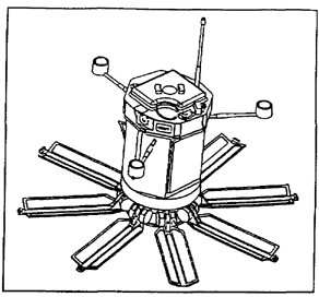
1-1. General. The M93 Hornet is an antitank (AT)/antivehicular smart munition made of lightweight material (35 pounds) that one person can carry and employ (Figure 1-1) . It is a one-time use, nonrecoverable munition that is capable of destroying vehicles by using sound and motion detection methods. It will automatically search, detect, recognize, and engage moving targets by using top attack at a standoff distance up to 100 meters from the munition. It is employed by combat engineers, ranges, and special-operations forces (SOF) that are equipped with an M71 remote control unit (RCU).
a. The RCU is a hand-held encoding unit that interfaces with the Hornet when the remote mode is selected at the time of employment After encoding, the RCU can be used to arm the Hornet, reset its self-destruct (SD) times, and destroy it.
Figure 1-1. M93 Hornet
b. Current Hornet systems are not as effective in extreme cold weather. High winds and extreme cold reduce the Hornet's ability to detect targets at maximum range. Radio-frequency jamming devices (such as the hand-emplaced, expandable jammer [HEXJAM]) limit the Hornet's communication capabilities if they re placed in the munition field, but they will not affect the Hornet's ability to engage targets and will not damage the system. Radio-frequency jamming devices affect the remote arming of current Hornet systems using the MOPMS RCU, and they will affect future Hornet's two-way communications capability with the Centurion remote control device.
c. The future Hornet will introduce an entirely new concept to the combined arms team. It will report enemy vehicles and categorize them by type. It can be ordered or programmed to develop coordinated attacks with other minefields and direct- and indirect-fire weapons. The future Hornet will have an inactivation feature that allows freedom of maneuver through the minefield or obstacle while still providing near real-time intelligence and situational awareness.
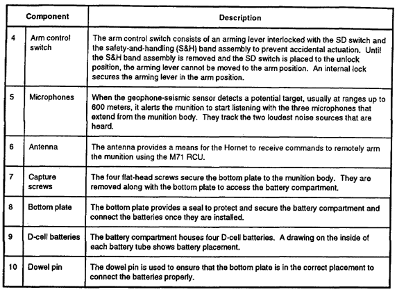
1-2. Major Components, Controls, and Procedures. Refer to Table 1-1 for the major components of the Hornet.
1-3. Controls and Indicators. Refer to Table 1-2, for information about the controls and indicators of the Hornet.
Table 1-1. Hornet components
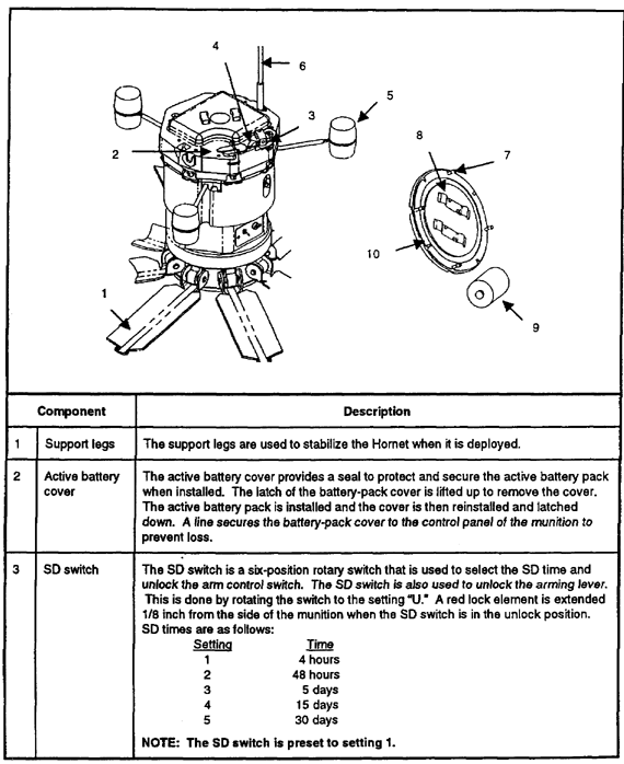
Table 1-1. Hornet components (continued)
1-4. Employment Considerations. The Hornet's active battery pack is inserted during prearming and has an estimated life of 4 hours. The active battery pack powers the munition from the time it is inserted until the end of the safe-separation time, when the built-in reserve battery is activated. To prevent munitions from becoming dud, do not prearm them too early. Allow enough time for traveling to the obstacle site, emplacing mines, throwing arming switches, ad permitting self-separation times to expire.
Table 1-2. Hornet controls and indicators
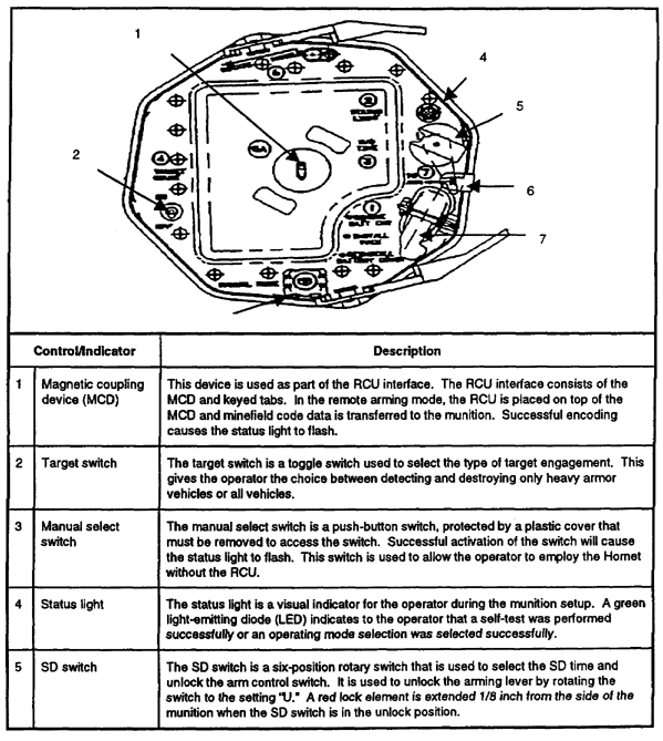
Table 1-2. Hornet controls and indicators (continued)

b. Hornet munitions have an employed life of 60 days in the prearmed mode (remote arming) and 30 days in the armed mode. If the temperature exceeds 100 degrees Fahrenheit, the employed life drops to 15 days in the prearmed mode and 30 days in the armed mode. Munitions placed at ground level should be no closer to obstructions than the distances shown in Table 1-3.
Table 1-3. Employment distances

c. The Hornet—
- Cannot distinguish between friendly or threat tracked vehicles.
- Can only operate on slopes up to 15 degrees (27 percent slope).
- Cannot operate in snow depths greater than 8 inches.
1-5. Employment Roles. Combat engineers or maneuver forces under engineer supervision emplace Hornets in close operations. SOFs or rangers emplace Hornets in deep operations. Hornets will be used throughout the entire depth of the battle space to support Army operations.
a. Close operations. In close operations, the Hornet can be—
- Used to fix the enemy and weaken it along its avenue of approach.
- Emplaced as an offensive-support weapon system because of its quick emplacement time and wide attack area.
- Employed rapidly along exposed flanks during a maneuver as a situational obstacle to disrupt the enemy's counterattacks.
- Used as a stand-alone tactical obstacle or as a reinforcement to other conventional obstacles.
- Used to disrupt and delay the enemy, allowing long-range precision weapons to engage more effectively. This feature is particularly effective in non-line-of-sight engagements.
b. Deep operations. In deep operations, the Hornet can be—
- Emplaced along key routes in gauntlet obstacles to disrupt and delay threat second-echelon forces, resupply operations, and key lines of communication.
- Used at command and control (C2) and logistics sites to disrupt enemy operations.
c. Rear operations. In rear battle, the Hornet can be emplaced (unarmed) along key routes in preparation for possible retrograde operations.
d. Early-entry operations. In early-entry operations, the Hornet can be—
- Used as an additional antiarmor weapon to supplement light forces.
- Used along high speed avenues of approach in gauntlet obstacles to buy time and space.
1-6. Tactical Emplacement. There are four basic emplacement scenarios or the Hornet. They are conventional minefield reinforcement, scatterable minefield reinforcement, area-disruption obstacle, and gauntlet obstacle.
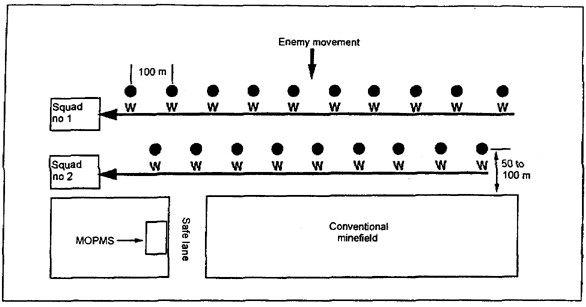
a. Conventional minefield reinforcement. The Hornet can be used to reinforce a conventional turn, block, or fix minefield (Figure 1-2) . Platoon engineers emplace the Hornet minefield as follows:
(1) Mine dumps.
(a) Hornet pallets are picked up at a brigade ammunition transfer point and transported on a heavy expanded mobility tactical truck (HEMTT) to the mine dump.
(b) Engineer units remove the Hornets from their packaging. If time allows, the munitions are prearmed and then loaded in two emplacement vehicles (normally combat engineer squad vehicles) using approved blocking and bracing procedures. While this is being done, the third squad and the platoon sergeant will site and mark the minefield, to include conventional and Hornet rows.
Figure 1-2. Hornet reinforcing a conventional minefield
(c) Two emplacement vehicles travel 20 to 40 kilometers per hour (on a road) or 15 kilometers per hour or less (cross-country) to the minefield site.
(2) Minefield emplacement site.
(a) Engineers emplace the conventional minefield first, and then they traverse the safe lane that is perpendicular to the minefield. The Hornets are employed in two staggered rows, spaced 100 meters apart, 50 to 100 meters from the front edge (on the enemy side) of the conventional minefield. The emplacing vehicles work towards the safe lane.
(b) Two squads employ Hornets in two rows of ten each. One or more soldiers provide security. Under the supervision of a noncommissioned officer (NCO) , four soldiers in each squad vehicle start prearming the Hornets, if necessary. They—
- Rotate the handle
- Remove the cover.
- Insert the active battery pack and verify functionality via a solid status light.
- Reinstall the active battery-pack cover.
- Select the SD time.
- Encode the Hornet with the M71 RCU and verify proper coding via a flashing status light.
- Reinstall the cover.
(c) Each emplacement vehicle moves to the first Hornet emplacement site in each row. The emplacing soldier and the arming soldier dismount. The emplacing soldier is handed a Hornet from the vehicle. He emplaces the Hornet at the designated spot, grabs the marking stake, and returns to the vehicle.
(d) The arming soldier rotates the handle on the Hornet, removes the cover and the S&H band, rotates the SD switch to U (the arm switch unlock position) , and pushes the arm switch to ARM. He then returns to the vehicle, taking the cover and the S&H band with him. The vehicle travels to the next Hornet emplacement site.
NOTE: Hornets can be remotely armed 36 minutes after the arming switch is thrown on the last Hornet emplaced. If manual arming is used, Hornets automatically arm at the end of their safe-separation time (5 to 6 minutes after the arming switch is thrown) .
Vehicles must wait at least 36 minutes after the last Hornet has its arming switch thrown before the Hornets are remotely armed with the M71 RCU. Hornets are now capable of covering the minefield by fire and engaging threat tracked vehicles (such as breachers or tanks) .
b. Scatterable minefield reinforcement. The Hornet can be used to reinforce a turn, block, or fix scatterable minefield (Figure 1-3). Platoon engineers emplace the Hornet minefield as follows:
(1) Mine dump. Refer to the procedures outlined in paragraph 1-6a(1).
(2) Minefield emplacement site. Refer to the procedures outlined in paragraph 1-6a(2). The Volcano dispensing vehicle can begin emplacing mines once all the Hornets are emplaced. To ensure that the Volcano dispensing vehicle has sufficient time to reach the safe standoff distance (475 meters) , Volcano dispensing should start no later than 30 minutes (minus the Volcano dispensing time [DT]) after the first Hornet's arming switch is thrown. Refer to paragraph 1-6a(2) (e) .
Figure 1-3. Hornet reinforcing a Volcano minefield
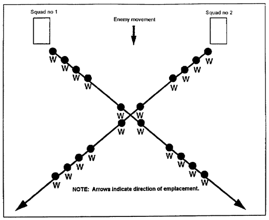
c. Area-disruption obstacles. When the X-pattern is employed, the Hornet is very effective as a disrupting obstacle (see Figure 1-4) . An area-disruption obstacle is employed to disrupt the enemy's approach before the start of the direct-fire battle. It causes disruption and attrition of the advancing threat force and encourages follow-on forces to seek an alternate route. Therefore, multiple area-disruption obstacles will typically be employed to adequately cover the cross-country avenue of approach. This requires coordinated action among multiple squads. Ensure that no soldiers are within 475 meters of armed Hornets. An engineer platoon emplaces the Hornet area-disruption obstacle as follows:
(1) Mine dump.
(a) Hornet pallets are picked up at a brigade ammunition transfer point and transported on a HEMTT to the mine dump.
(c) The emplacement vehicles travel 20 to 40 kilometers per hour (on a road) or 15 kilometers per hour or less (cross-country) to the site of the Hornet area-disruption obstacle. The area-disruption obstacle will be located up to a maximum of 5 kilometers from the mine dump. It will be employed beyond the range of friendly direct fires, with the intention of disrupting the enemy's approach while it is traveling in prebattle formation. Two squad vehicles will go to the emplacement sites for the two clusters closest to the enemy. The third squad vehicle will provide overwatch or security on the friendly side of the obstacle.
Figure 1-4. Hornet area-disruption obstacle
(2) Area-disruption obstacle emplacement site.
(a) An engineer platoon emplaces a Hornet area-disruption obstacle. The obstacle typically consists of 20 Hornets (five clusters of four Hornets each) employed in an X-pattern over a 1- by 1-kilometer area. Individual Hornets are emplaced about 100 meters apart. Emplacing this obstacle must be done as a dispense-and-roll operation to ensure that the emplacing vehicles can reach the safe standoff distance (475 meters) from any armed Hornets.
(b) Hornets are prearmed as outlined in paragraph 1-6a(2)(b).
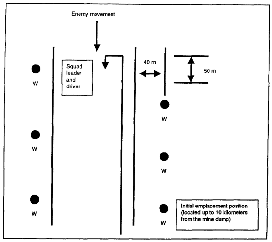
d. Gauntlet obstacles. The high-explosive Hornet can be used as a gauntlet obstacle (see Figure 1-5) . This pattern is effective in constricted terrain along the enemy's avenue of approach. An engineer platoon emplaces the Hornet gauntlet obstacle as follows:
Figure 1-5. Hornet gauntlet obstacle (one cluster)
(1) Mine dump.
(a) Hornet pallets are picked up at a brigade ammunition transfer point and transported on a HEMTT to the mine dump.
(b) Refer to paragraph 1-6c(l)(b), for packaging removal and loading. Before this is done or while it is being done, one squad and the platoon sergeant will site and mark the gauntlet obstacle or at least do a map reconnaissance to determine duster locations, munition settings for each duster, and if time permits, the number and location of individual Hornets in each cluster.
(c) The emplacement vehicles travel 20 to 40 kilometers per-hour (on a road) or 15 kilometers per hour or less (cross-country) to the site of the first cluster in the Hornet gauntlet obstacle (the one closest to the enemy) . The first cluster in the Hornet gauntlet obstacle may be located several kilometers away (up to 10 kilometers or more) from the mine dump.
(2) Gauntlet obstacle emplacement site.
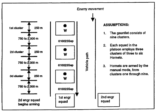
(a) Hornet gauntlet obstacles are emplaced by an engineer platoon along likely threat high-speed avenues of approach and at choke points. A Hornet gauntlet typically consists of 40 to 50 Hornets employed in a series of clusters. Each cluster contains 3 to 6 Hornets. The Hornets in each cluster are emplaced at 50-meter intervals, perpendicular to the road centerline, on alternating sides of the road/avenue of approach, and 25 to 40 meters (depending on the terrain and vegetation) off the side of the road/avenue of approach. The distance between clusters varies from 750 to 2,000 meters so that the advancing threat force is kept guessing about when they will encounter the next cluster (Figure 1-6) .
Figure 1-6. Hornet gauntlet obstacle (platoon)
(b) Before laying any Hornets, the munitions will be prearmed as stated in paragraph 1-6a (2) (b). Soldiers also set the target switch to HVY for clusters closest to the enemy so that the Hornets will only engage heavy tracked vehicles. Soldiers select manual arming by removing a protective tab, depressing the manual-mode select switch (a push button), verifying functionality via a flashing status light, and reinstalling the tab.
(c) Hornets are emplaced beginning on the friendly side of the cluster. The first engineer squad emplaces Hornet munitions beginning with the cluster closest to the enemy. The emplacement vehicle drives even with the first Hornet emplacement site. The emplacing soldier dismounts, and a soldier in the vehicle hands him a Hornet. The emplacing soldier then proceeds to the Hornet emplacement site.
(d) The vehicle travels to a point even with each subsequent emplacement site. A soldier deploys at each emplacing site to lay one of the remaining Hornet munitions in the cluster. The vehicle then turns around and stops even with the last Hornet (on the enemy side) in the cluster.
(e) Upon reaching the Hornet employment location, each emplacing soldier removes the cover and S&H band, rotates the SD switch to U (the arm control switch's unlock position) , and on the command (audible or visual signal) of the noncommissioned officer in charge (NCOIC) , pushes the arm switch to ARM. Once the Hornets' arming switches are thrown, soldiers return to the road, taking the covers and the S&H bands with them, and wait to be picked up by the emplacement vehicle. After all of the soldiers are in the emplacing vehicle, the driver quickly travels to the safe standoff distance (475 meters) . The Hornet munitions in the first cluster will arm at the end of the safe-separation time (5 to 6 minutes) . The squad repeats the emplacement process for the next Hornet cluster in the gauntlet, taking care not to emplace any Hornets or drive within 475 meters of the previous cluster. Each squad in the platoon typically emplaces three clusters in the Hornet gauntlet, or 9 to 18 total Hornets.
1-7. Recording and Marking. When the Hornet munition field is completed, the officer in charge (OIC) will identify an NCO to be the recorder. The NCO will collect data from the NCOICs of the emplacing squads and complete Department of the Army (DA) Form 1355 as outlined in Chapter 8 of FM 20-32. An example of the DA Form 1355 is shown in Figure 1-7. The OIC will ensure that the DA Form 1355 is completed on time and is accurate.
Marking the Hornet munition field will be completed as prescribed in Chapter 2 of FM 20-32. The fence will be no closer than 150 meters from the nearest Hornet munition. Marking must be completed before emplacing the munitions.
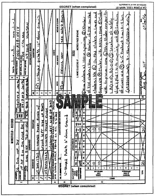
Figure 1-7. Sample DA Form 1355 (front side) for a Hornet minefield/munition field.
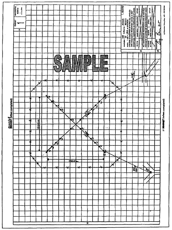
Figure 1-7. Sample DA Form 1355 (front side) for a Hornet minefield/munition field (continued)
GO TO:


