

|
RDL Homepage |
Table of Contents |
Document Information |
Download Instructions |
LESSON 2
TRENCHES AND FIELDWORKS
LESSON OBJECTIVES
Upon completion of this lesson, you should be able, in the indicated topic areas, to —
1. Trench Types. Describe the construction of the crawl trench, the fighting trench, and the standard trench.
2. Traces. Describe the octagonal and zigzag traces and know the advantages of each type of trace in trench layout.
3. Trench Drainage. Describe construction of trenches to keep out surface runoff, dispose of rainfall and seepage, and reroute natural drainage channels.
4. Trench Overhead Cover. Describe the construction of light and heavy overhead cover.
5. Trench Revetment. Discuss construction of the facing type, brushwood hurdle, continuous brush, pole and dimensioned timber, and metal types of revetments.
6. Revetments and Breastworks. Discuss the use of sandbags, sod blocks, and expedients. Describe the construction of breastworks.
7. Defenses in Tropical Areas. Discuss considerations necessary when constructing defenses in tropical areas.
8. Tunneled Defenses. Discuss soil, terrain, timbering, entrances, and ventilation of tunneled defenses.
ATTACHED MEMORANDUM
Section I. Trenches
2-1. PURPOSE
a. Defensive area. Trenches are excavated as fighting positions and to connect individual foxholes, weapons emplacements, and shelters in the progressive development of a defensive area. They provide protection and concealment for personnel moving between fighting positions or in and out of the area. Trenches should be included in the overall layout plan for the defense of a position. The excavation of trenches involves considerable time, effort, and materials and is only justified when an area will be occupied for an extended period. Trenches are usually open excavations but sections may be covered to provide additional protection if the overhead cover does not interfere with the fire mission of the occupying personnel. Trenches are difficult to camouflage and are easily detected, especially from the air.
b. Development. Trenches are developed progressively as is the case for other fighting positions. As they are improved, they are dug deeper, from a minimum of 60 cm (2 ft) to approximately 1.7 meters (5 l/2 ft). As a general rule, there is a tendency to excavate deeper for other than fighting trenches to provide more protection or to allow more headroom. Some trenches may also have to be widened to accommodate more traffic, including stretchers. It is usually necessary to revet trenches that are more than 1.5 meters (5 ft) deep in any type of soil. In the deeper trenches some engineer advice or assistance may be necessary in providing adequate drainage.
2-2. CONSTRUCTION
a. Crawl trench. The crawl trench is used to conceal movement into or within a position, and to provide a minimum of protection. Crawl trenches should be 60 to 75 cm (24 to 30 in.) deep and about 60 cm (24 in.) wide. This trench is the narrowest practicable for most purposes and of the least width that can be dug without difficulty. It should be zigzagged or winding. The spoil is placed on the parapets, normally on each side of the trench. If the trench runs across a forward slope, it is better to place all the spoil on the enemy side to make a higher parapet.
b. Fighting trench. In developing a trench system, the outline of the trench is marked out on the ground if time permits; if the digging is to be done at night, the ground is taped. The berm line is indicated about 45 cm (18 in.) from the front edge of the trench. The trench is dug by men working in the same direction (not facing each other or back to back), and far enough apart so that they do not interfere with each other.
(1) First step. The trench is dug to a depth of 90 cm (3 ft.) below ground level (1, fig 2-1). At this point both men are able to fire in either direction, in a kneeling or crouching position. In ordinary soil this step can be completed in approximately 2 hours. The sides of the trench are kept vertical, or as steep as possible. If the soil is not stable, the sides require revetting immediately. Spoil is placed on each side of the trench in alternate shovelfuls beyond the berm lines until each parapet is about 30 cm (12 in.) high and at least 45 cm (18 in.) wide on the back parapet. The remaining spoil is placed on the front parapet until it is at least 150 cm (5 ft.) wide (fig 2-1).
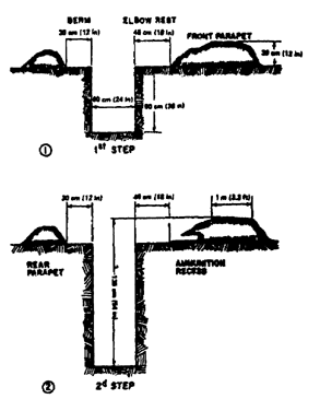
Figure 2-1. Development of a fighting trench.
(2) Second step. The second step consists of deepening the trench until it is approximately 1.35 meters (4 l/2 ft.) deep from the level of the trench parapet (2, fig 2-1). Normally, the front parapets are 30 cm (12 in.) high and the dirt settles 5 to 10 cm (2 to 4 in.). Parapets are then shaped and camouflaged.
(3) Front parapet. The front parapet must be made according to the lay of the ground and the requirements of the weapon. A front parapet is often unnecessary on a steep forward slope. At most sites a front parapet improves the field of fire and should be constructed as follows:
(a) Height. A convenient height for the front parapet for firing purposes is 23 to 30 cm (9 to 12 in.) when the ground is level. It should be higher to fire uphill and the crest should be irregular to aid concealment. The height shown in figure 2-1 is average.
(b) Width. A reasonably bulletproof parapet should be 1 meter in width. Since it is sloped in front and rear, the total width on the bottom will be approximately 2 meters (6.5 ft.).
(c) Berms. The berm on the front of the trench forms an elbow rest which is usually about 45 cm (18 in.) wide. If an M60 machinegun on a bipod is to be fired, the firing platform should be 90 cm (36 in.) from front to rear.
(4) Rear parapet. The rear parapet is made of spoil that is not required for the front parapet. If the spoil is available the rear parapet should be higher than the front parapet to prevent silhouetting of soldiers' heads when firing. The rear parapet may be up to 45 cm (18 in.) high and should be at least 45 cm (18 in.) wide at the top, sloped steeply in front. Parapets may be omitted to aid concealment or when ground provides background and protection to the firer's rear.
(5) Concealment. Parapets are finished off by replacing turf or topsoil. The trench and parapets are covered with any available camouflage material, arranged to permit firing.
(6) Drainage. A sump is dug at the lowest point to prevent the floor of the trench from becoming wet and muddy.
c. Standard trench. The standard trench is developed from the fighting trench by lowering it to a depth of 1.7 meters (5 l/2 ft.). It may be constructed with fighting bay (fig 2-2) or with a fighting step (fig 2-3). Fighting positions are constructed on both sides of the trench to provide alternate positions to fight to the rear, to provide step off areas for foot traffic in the trench, and to provide protection against enfilade fire. The trench provides more protection than the fighting trench due to its depth. Additional protection in the form of overhead cover may also be provided. This trench is primarily a fighting position, but it can also be used for communications, supply, evacuation, and troop movements.
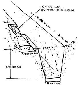
Figure 2-2. Standard trench with fighting bay.
d. Traces. Each trench is constructed to the length required and follows one of the traces described below to simplify construction. Special combinations and modifications may be developed.
(1) Octagonal trace. The octagonal trace (1, fig 2-4) is excellent for fighting trenches in most situations. The octagonal trace has the following advantages:
(a) It affords easy communication.
(b) It affords excellent protection against enfilade fire.
(c) It facilitates oblique fire along the front.
(d) It is economical to construct, both in labor and material.
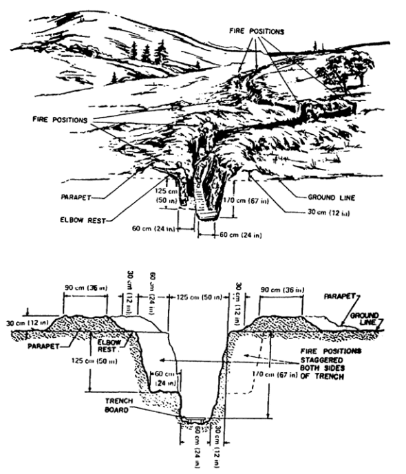
Figure 2-3. Standard trench with fighting step.
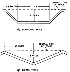
Figure 2-4. Standard trench traces.
(e) It can be provided with a continuous fire step. Its chief disadvantage is that its layout lacks simplicity of detail.
(2) Zigzag trace. The zigzag trace (2, fig 2-4) can provide protection from enfilade fire and shell bursts by the employment of short tangents, and by the occupation of alternate tangents. The zigzag trace has the following advantages:
(a) It is the simplest and easiest to trace, construct, revet, and maintain.
(b) It may be readily adapted to the terrain.
(c) It permits both frontal and flanking fire.
(d) This trace has no specific disadvantages.
e. Trench boards. If the sumps are choked with mud, they will cease to function. When this happens, alternatives include some forms of flooring. Trench boards (fig 2-5) are the most practical. Timber planks, metal mats, or saplings wired together may also be used.
2-3. DRAINAGE.
a. Siting. Emplacements, shelters, and trenches are sited to take advantage of the natural drainage pattern of the ground. They are constructed to provide for—
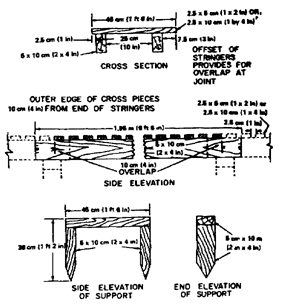
Figure 2-5. Trench board and support.
(1) Exclusion of surface runoff.
(2) Disposal of direct rainfall or seepage.
(3) Bypassing or rerouting natural drainage channels if they are intersected by the emplacement or shelter.
b. Surface runoff. Proper siting, as illustrated in figure 2-6, can lessen the problem of surface runoff by locating the emplacement, shelter, or trench in an area not subject to excessive runoff. Surface water may be excluded by excavating interceptor ditches upslope from the emplacement or shelter. It is much easier to prevent surface water from flowing in than to remove it after it is in the excavation. Fortifications should be sited so as to direct the water to natural drainage lines. If this is not possible, the water is conducted across the trench through open flumes developed for the purpose or under the trench using a combination of trench drains and culverts. An application of the open flume method for use with trenches is shown in figure 2-7. A typical undertrench drain is shown in figure 2-8.
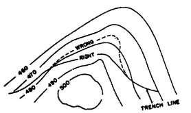
Figure 2-6. Siting to lessen problem of runoff disposal.
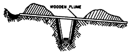
Figure 2-7. Use of open flume to direct water across ditch.
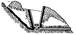
Figure 2-8. Use of undertrench drains.
c. Direct rainfall or seepage. Water collecting within an emplacement or shelter is carried to central points by providing longitudinal slopes in the bottom of the excavation. A very gradual slope of 1 percent is desirable. In trenches the slope is best provided for by fitting the trench to the terrain in such a way that the original surface has a moderate slope, as shown on the contoured layout in figure 2-9. When permitted by the tactical situation, excavation of trenches should commence at the lowest level and progress upward in order to avoid collecting water in the bottom of a partially completed trench. The central collecting points may be either natural drainage lines or sumps below the bottom of the excavation as shown in figure 2-10. Such sumps are located at points where the water will percolate through permeable soil or can be piped, pumped, or bailed out.
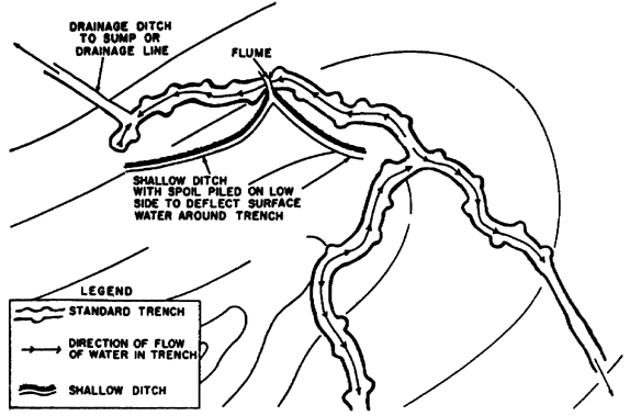
Figure 2-9. Method of siting trench to provide longitudinal drainage.
Figure 2-10. Drainage sump in bottom of excavation.
2-4. OVERHEAD COVER
a. Light cover. Expedient overhead cover may be supported as shown in figure 2-11. Logs 15 to 20 cm (6 to 8 in.) in diameter should be used to support light earth cover. Saplings laid in a laminated pattern to a depth of 15 to 20 cm (6 to 8 in.) may be used as a substitute for the logs. The total thickness of the logs or saplings and the earth cover should be a minimum of 45 cm (18 in.)
b. Heavy cover. If heavy overhead cover is used in the construction of trenches, it should be installed in 6- to 12-meter (20 to 40 ft.) sections and in conjunction with the cover of emplacements and shelters connected by the trenches. Support for heavy overhead cover is provided by post-cap-stringer type structures as shown in figures 2-12 and 2-13. Trenches must be widened and deepened to accommodate these structures in accordance with information contained in the above illustrations. Bills of materials are shown in tables 2-1 and 2-2.

Figure 2-11. Revetted fighting trench with cover.
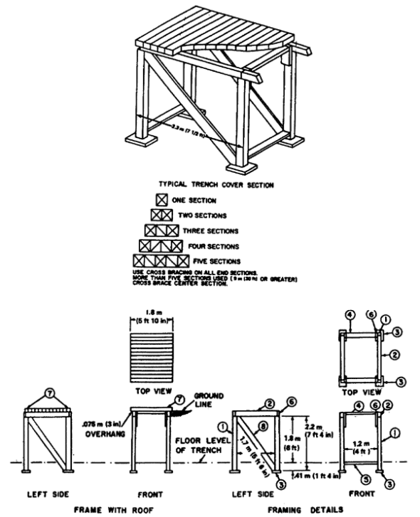
Figure 2-12. Trench cover section, dimensioned timber.
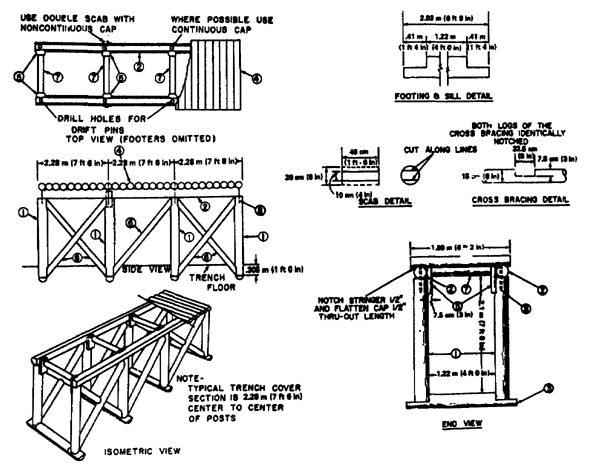
Figure 2-13. Trench section, log construction.
2-5. REVETMENT
a. Wall sloping. The necessity for revetment may sometimes be avoided or postponed by sloping the walls of the excavation. In most soils a slope of 1:3 or 1:4 is sufficient. This method may have to be used temporarily if the soil is loose and revetting materials are not available. Wall sloping can seriously reduce the protection due to the increased width of the trench at ground level. In any case where wall sloping is used, the walls should be dug vertical first and then sloped. Multiply the height of the wall as in figure 2-14 by the slope to be used 1:4 (l/4). This gives the amount the wall must be cut back at ground level. Then, cut out a section about 30 cm (12 in.) wide for a guide, as shown.
b. Facing type revetment. Facing revetment serves mainly to protect revetted surfaces from the effects of weather and damage caused by occupation. It is used when soils are stable enough to sustain their own weight. This revetment (fig 2-15) consists of the revetting or facing material and the supports which hold the revetting material in place. The facing material may be much thinner than that used in a retaining wall. For this reason facing type revetments are preferable since less excavation is required. The top of the facing should be set below ground level so the revetting is not damaged by tanks crossing the emplacement.
(1) Materials for facing. The facing may be constructed of brushwood hurdles, continuous brush, pole and dimensioned timbers, corrugated metal, or burlap and chicken wire. The method of constructing each type is described below.
Table 2-1. Bill of Materials, Trench Cover Section, Post, Cap, and Stringer, Construction Dimensioned Timber.

Table 2-2. Bill of Materials, Trench Cover Section, Post, Cap, and Stringer, Construction Log.
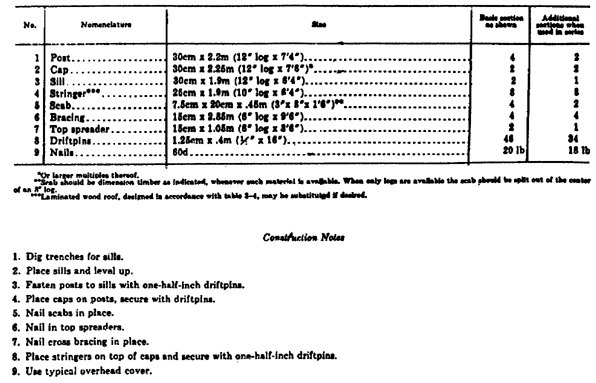
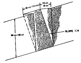
Figure 2-14. Method of sloping earth walls.
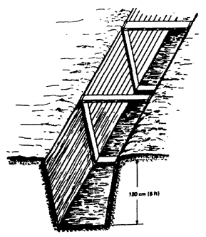
Figure 2-15. Facing revetment supported by frames.
(2) Methods of support. The facing may be supported by —
(a) Timber frames. Frames of dimensioned timber are constructed to fit the bottom and sides of the position, and hold the facing material apart over the excavated width.
(b) Pickets. Pickets are driven into the ground on the position side of the facing material and held tightly against the facing as shown in figure 2-16 by bracing the pickets apart across the width of the position and anchoring the tops of the pickets by means of stakes driven into the ground and tiebacks.
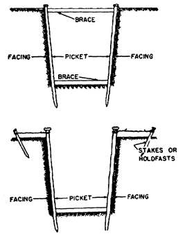
Figure 2-16. Facing revetment supported by pickets.
(3) Facing type revetments. Facing type revetments may be supported either by timber frames or pickets. The size of pickets required, and their spacing, are determined by the soil and the type of facing materials used. Wooden pickets should not be smaller than 7.5 cm (3 in.) in diameter or in the smallest dimension. The maximum spacing between pickets should be about 2 meters (6.5 ft.). The standard pickets used to support barbed wire entanglements are excellent for use in revetting. Pickets are driven at least 45 cm (18 in.) into the floor of the position. equal to the height of the revetted face, with alternate anchors staggered and at least 60 cm (24 in.) farther back. Several strands of wire holding the pickets against the emplacement walls must be straight and taut. A groove or channel is cut in the parapet to pass the wire through.
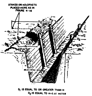
Figure 2-17. Method of anchoring pickets.
c. Brushwood hurdle. A brushwood hurdle is a woven revetment unit usually 2 meters (6.5 ft.) long and of the required height. As shown in figure 2-18, pieces of brushwood about 2.5 cm (1 in.) in diameter are woven on a framework of sharpened pickets driven into the ground at 50 cm (20 in.) intervals. When completed, the 2-meter (6.5 ft.) lengths are carried to the position, where the pickets are driven in place and the tops of the pickets are tied back to stakes or holdfasts. The ends of the hurdles are then wired together.
d. Continuous brush. As shown in figure 2-19, a continuous brush revetment, which is constructed in place. Sharpened pickets, 7.5 cm (3 in.) in diameter, are driven into the bottom of the trench at 1-pace intervals and about 10 cm (4 in.) from the earth face to be revetted. The space behind the pickets is packed with small straight brushwood laid horizontally and the tops of the pickets are anchored to stakes or holdfasts.

Figure 2-18. Making a brushwood hurdle.
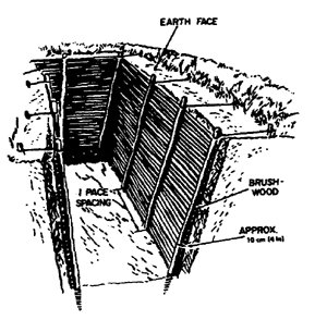
Figure 2-19. Continuous brush revetment.
e. Pole and dimensioned timber. A pole revetment (fig 2-20) is similar to the continuous brush revetment except a layer of small horizontal round poles, cut to the length of the wall to be revetted, is used instead of brushwood. Instead of poles, boards or planks are used if available; they have the added advantage of being more quickly installed. Pickets are held in place by holdfasts or struts.
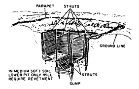
Figure 2-20. Timber revetment using small poles.
f. Metal. A revetment of corrugated metal sheets, (![]() , figure 2-21) or pierced steel plank may be installed rapidly and is strong and durable. It is well adapted to emplacement construction because the edges and ends of sheets or planks can be lapped as required to produce a revetment of a given height and length. All metal surfaces must be smeared with mud to eliminate possible reflection of thermal radiation and to aid in camouflage. Burlap and chicken wire revetments are installed as shown in (
, figure 2-21) or pierced steel plank may be installed rapidly and is strong and durable. It is well adapted to emplacement construction because the edges and ends of sheets or planks can be lapped as required to produce a revetment of a given height and length. All metal surfaces must be smeared with mud to eliminate possible reflection of thermal radiation and to aid in camouflage. Burlap and chicken wire revetments are installed as shown in (![]() , figure 2-21). When damaged, corrugated metal forms dangerous sharp edges. Prompt attention should be given to the repair of damaged revetments to prevent injuries to personnel or damage to equipment.
, figure 2-21). When damaged, corrugated metal forms dangerous sharp edges. Prompt attention should be given to the repair of damaged revetments to prevent injuries to personnel or damage to equipment.
2-6. Repair and Maintenance of Trenches
a. Maintenance.
(1) Drainage. It is important to keep the drainage system working properly. If water is allowed to stand in the bottom of a trench, the revetment will eventually be undermined and become useless. Sumps and drains must be kept clear of silt and refuse. Trench boards should be lifted periodically so that the mud can be cleaned out from beneath them.
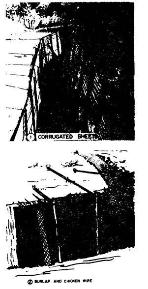
Figure 2-21. Types of metal revetment.
(2) Berms. Berms must be kept clear and of sufficient width to prevent soil from the parapets falling into the trench.
(3) Revetted trenches. When wire and pickets are used to support revetment material, the pickets may become loose, especially after rain. Improvised braces may be wedged across the trench at or near floor level, between two opposite pickets. Anchor wires may be tightened by further twisting. Anchor pickets may have to be driven in farther to hold the tightened wires.
(4) Sandbag revetments. Periodic inspections must be made of sandbags. Any bags that are split or damaged should be replaced.
b. Repair.
(1) Top of trench. If the walls are crumbling at the top, making the trench wider at ground level, an elbow rest should be cut out of the full width of the berm and about 30 cm (12 in.) deep, or until firm soil is reached. Sandbags or sods are then used to build up the damaged area (![]() , figure 2-22).
, figure 2-22).
(2) Bottom of trench. If the trench walls are wearing away at the bottom, place a plank on edge, or shift brushwood as shown in (![]() , figure 2-22). The plank is held against the trench wall with short pickets driven into the trench floor. If planks are used on both sides of the trench, they are held in position with a piece of timber cut to the right length and wedged between the planks at floor level. Earth is placed in back of the planks.
, figure 2-22). The plank is held against the trench wall with short pickets driven into the trench floor. If planks are used on both sides of the trench, they are held in position with a piece of timber cut to the right length and wedged between the planks at floor level. Earth is placed in back of the planks.
(3) Collapsed wall. If an entire wall appears to be collapsing, the trench must be completely revetted or the walls sloped (fig 2-14) so they will stand. If the walls are permitted to cave in, the trench usually must be widened at ground level which reduces its protective value. Cave-ins should be prevented as far as possible by revetting the trench in time or by one of the remedial measures described above.
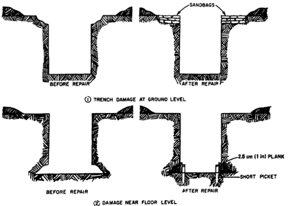
Figure 2-22. Trench repair.
Section II. Fieldworks
2-7. REVETMENTS
a. Use of sandbags. Walls are built of sandbags or sod in much the same way as bricks are used. Sandbags are also useful for temporary retaining wall type revetments, especially where silent installation is essential. The three types of sandbags in use are the cotton osnaburg, the polypropylene, and the acrylic. All are used in the same manner. The polypropylene bag will last approximately seven months, twice as long as the cotton osnaburg bag. The acrylic sandbag which is replacing the osnaburg and the polypropylene is rot and weather resistant. The bag under all climate conditions has a life of at least 2 years, with no visible deterioration. It is readily stacked to form a sandbag revetment or breastwork with no slippage of individual bags within the stack. Holes in a bag caused by a bullet or a fragment do not enlarge due to continued weakening or unravelling of the bag material around the hole or holes. The bag is lusterless olive drab in color. The useful life of sandbags can be prolonged by filling them with a mixture of dry earth and portland cement, normally in the ratio of 1 part of cement to 10 parts of dry earth. The cement sets as the bags take on moisture. A ratio of 1 to 6 should be used for a sand-gravel mixture. The filled bags may be dipped in a cement-water slurry as an alternative method. Each sandbag should be pounded with a flat object, such as a 5 by 10 cm (2 by 4 in.) board, to make the wall more stable.
(1) Construction. As a rule sandbags are used for revetting only when the soil is very loose and requires a retaining wall to support it or for the repair of damaged trenches. A sandbag revetment will not stand with a vertical face. The face must have a slope of 1:4 and the base must be on firm ground and dug at a slope of 4:1. The sandbag wall should lean against the earth if it is to hold in place (fig. 2-23).

Figure 2-23. Retaining wall revetment.
(b) The bottom corners of the bags are tucked in after filling.
(c) As the revetment is built, the revetted face is made to conform to this slope by backfilling or additional excavation.
(d) Sandbags are laid so that the planes between the layers have the same pitch as the foundation, i.e., at right angels to the slope of the revetment.
(e) The bottom row of the revetment is constructed with all bags placed as headers (fig 2-23). The wall is then constructed using alternate rows of stretchers and headers with the joints broken between courses. The top row of the revetment wall consists of headers.
(2) Common faults. The common faults in sandbag revetments are illustrated in figure 2-23.
(3) Expedient means of filling sandbags. Often the requirement for filled sandbags far exceeds the capabilities of men using shovels to fill sandbags. A high speed combat intrenching machine can be used to fill sandbags if local soil is to be used as the filler. The bag is filled by holding it under the discharge conveyor as the intrenching machine is run forward at a slow speed (fig. 2-24). This method will produce filled sandbags at a rate of one every four to five seconds. The spillage can be used to fill sandbags also since it is often loose and easily shoveled. If the sandbags are to be filled from a stockpile of sand or other material, the work can be made easier and the bags filled faster by using the funnel as shown in figure 2-25. The funnel can be constructed using either lumber or steel.
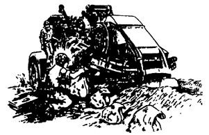
Figure 2-24. Use of combat intrencher to fill sandbags.
b. Sod blocks. Thick sod with good root systems provides a satisfactory revetting material. Sod blocks cut into sections about 23 by 46 cm (9 by 18 in.) are laid flat, using the alternate stretcher-header method described above for use with sandbags. Sod is laid grass-to-grass and soil-to-soil, except for the top layer which should be laid with the grass upward, to provide natural camouflage. As each layer of sod is completed, wooden pegs are driven through the layers to prevent sliding until the roots grow from layer to layer. Two pegs are driven through each 23 by 46 cm (9 by 18 in.) sod. Sod revetment is laid at a slope of about 1 horizontal to 3 vertical.
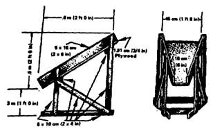
Figure 2-25. Expedient funnel for filling sandbags.
c. Expedients. In cold weather blocks of ice may be used to construct retaining wall type revetments. They are stacked in the same manner as sandbags or sod. Water is applied to bind them together by freezing. Other expedients include earth-filled packing cases or ammunition boxes. Empty boxes or packing cases are placed in position and nailed to the lids of the layer below; the boxes and filled with earth or rock and the lids fastened in place. This procedure is repeated for each row. The tops of the revetment are tied to pickets to prevent overturning.
2-8. BREASTWORKS
Breastworks may be substituted for trenches, weapons emplacements, etc., when soil conditions or a high water table makes excavation to the required depth impossible. Under these circumstances earth must be built up above ground level to form protective walls. This work requires more time and effort than digging trenches of comparable depth. Breastwork defenses are not as good protection against airbursts as excavated positions. They also have serious disadvantages against blast and nuclear radiation.
a. Construction. When breastworks are constructed for fire positions and weapons emplacements their dimensions should conform to the excavated positions. A front breastwork should be bulletproof, i.e., of approximately 1 meter (3.3 ft.) minimum thickness. The outer face should be sloped gently; not steeper than 1:2 (fig 2-26). The inner face should be sloped 1:4 and revetted. A rear breastwork may be similar to the front.
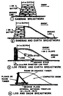
Figure 2-26. Varied types of breastworks.
b. Snow breastworks. Snow breastworks can be constructed as shown in ( , figure 2-26).
2-9. SNOW DEFENSES
a. Snow as protective material. Snow must be packed to be effective against small arms fire. Drifted snow is usually well compacted by the wind. Loose snow has only about half the value of packed snow in resisting penetration, but shells and grenades bursting on impact are largely ineffective in loose snow because the fragmentation is blanketed. The thickness of snow required for protection against small arms and shell splinters is as follows:
| Newly fallen snow | At least 4 meters (13 ft) |
||
| Firmly frozen snow | At least 2.5-3 meters (8-10 ft.) |
||
| Packed snow | At least 2 meters (6 l/2 ft.) |
||
| Ice | At least 30 cm (12 in.) |
b. Trenches. In deep snow, trenches and weapons emplacements may be excavated in the snow to approximately normal dimensions. Unless the snow is well packed and frozen, revetment will be required, ( , figure 2-26). In shallow snow, not deep enough to permit excavation to the required depth, snow breastworks must be constructed. These should be of compacted snow, at least 2 meters (6 l/2 ft.) thick and revetted.
2-10. Defenses in Tropical Areas
a. Advantages.
(1) Concealment is comparatively easy.
(2) Timber is readily available.
b. Tools. A variety of cutting tools are required to —
(1) Clear fields of fire.
(2) Cut tree roots during excavation.
(3) Cut timber for overhead cover.
c. Equipment. When large cleared areas are necessary bulldozers with winches or dozers with land clearing blades are required for grubbing trees. Bulldozers can clear from 10,000 to 12,000 square meters (11,960 to 14,350 sq. yd.) of heavy jungle is 8 hours. Dozers with land clearing blades can clear 15,000 to 25,000 square meters (17,940 to 29,900 sq. yd.) of heavy jungle in the same length of time.
d. Drainage. Good drainage is required for all excavations and should be considered in the initial siting of the position. Trenches, shelters, and emplacements are floored as soon as possible. Stone, brushwood covered with bamboo matting may be used.
e. Overhead cover. Waterproof material such as building paper should be included in the overhead cover for shelters or trenches and should overlap the sides of the structure about 60 cm (2 ft.). Material used as overhead cover must be well supported and sloped so water will run off.
2-11. DUMMY EARTHWORKS
a. Dummy trenches. Dummy trenches are dug to conceal the true extent of a defended area or locality. Dummy trenches should be dug about 45 cm (18 in.) deep, with brushwood laid in the bottom, ( , fig 2-27). The brushwood has the effect of producing an internal shadow similar to that cast by a deep trench. Parapets must be similar to those of other trenches in the position. False parapets should also be concealed.
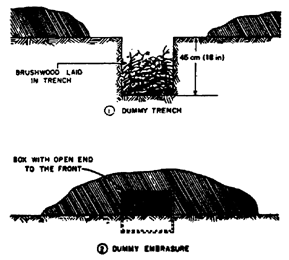
Figure 2-27. Dummy earthworks.
b. Dummy emplacements. The most noticeable feature of a roofed emplacement is the deep internal show of its embrasure. This appears to the enemy from the ground as a black patch of regular shape. Usually, it will appear rectangular if the roof is flat. A rectangular embrasure can be simulated by means of a box placed in the ground, with open end to the front, and covered with earth ( ,
fig 2-27). Some attempt at concealment and occasional signs of occupation will add realism.
,
fig 2-27). Some attempt at concealment and occasional signs of occupation will add realism.
2-12. TUNNELED DEFENSES
a. Considerations. Tunnels are not used frequently in the defense of an area due to the time, effort, and technicalities involved; however, they have been used to good advantage. Tunneled defenses can be used when the length of time an area must be defended justifies the effort and the ground lends itself to this purpose.
b. Soil. The possibility of tunneling also depends to a great extent on the nature of the soil, which can be determined by borings or similar means. Tunneling in hard rock is so slow that it is generally impractical. Tunnels in clay or other soft soils are also impractical since they must be lined throughout or they will soon collapse. Construction of tunneled defenses is usually limited to —
(1) Hilly terrain - steep hillsides.
(2) Favorable soil, including hard chalk, soft sandstone, and other types of hard soil or soft rock.
c. Tunnel examples. A sketch of tunnels is shown in figure 2-28. In this tunnel system, the soil was generally very hard and only the entrances were timbered. The speed of excavation, using handtools, varied according to the soil, seldom exceeding 7.5 meters (25 ft.) per day. In patches of hard rock, as little as 1 meter (3.3 ft.) was excavated in a day (24 hr.). The use of powertools did not alter the speed of excavation significantly. The work was done by engineer units assisted by infantry personnel.
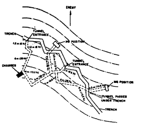
Figure 2-28. Tunneled defenses.
d. Construction. Tunnels of the type shown (fig 2-28) are excavated about 9 meters (30 ft.) below ground level. They may be horizontal or nearly so.
(1) Entrances. The entrances must be strengthened against collapse under shell fire and ground shock from nuclear weapons. The first 5 meters (16.5 ft.) from each entrance should be framed with timber supports using 10 cm x 10 cm (4 in. x 4 in.) or comparable timbers.
(2) Size. Untimbered tunnels should be about 1 meter (3.3 ft.) wide and 1.5 to 2 meters (5 to 6.5 ft.) high.
(3) Chambers. Chambers may be constructed in rock or extremely hard soil without timber supports. If timber is not used the chamber (fig 2-28) should not be more than 2 meters (6.5 ft.) wide. If timbers are used the width may be increased to 3 meters (10 ft.). The chamber should be the same height as the tunnel and up to 4 meters (13 ft.) long.
(4) Grenade trap. Grenade traps should be constructed at the bottom of straight lengths where they slope. It can be done by cutting a recess about 1 meter (3.3 ft.) deep in the wall facing the inclining floor of the tunnel.
(5) Disposal of soil. A considerable quantity of spoil from the excavated area must be disposed of and concealed. The volume of spoil is usually estimated as one-third greater than the volume of the tunnel. Approximately 100 tons of spoil were removed from the tunnel system shown in figure 2-28.
(6) Concealment. Tunnel entrances must be concealed from enemy observation and it may be necessary to transport spoil by hand through a trench. Cold air rising from a tunnel entrance may give away the position.
e. Precautions.
(1) Picks and shovels. There is always danger that tunnel entrances will be blocked, trapping the occupants. Picks and shovels must be kept in each tunnel so men trapped can dig their way out.
(2) Entrances. At least two entrances are necessary for ventilation purposes; whenever possible one or more emergency exits should be provided. These may be small tunnels whose entrances are normally closed and concealed; a tunnel may be dug from inside the system to within a few feet of the surface so a breakthrough can be made if necessary.
GO TO: