

LESSON 8
| LESSON 8 | Allison T63, Pratt & Whitney T73 and T74, and General Electric T700. |
| TEXT ASSIGNMENT | Reference Text AL0993, chapters 7, 8, 9, and 10. |
| LESSON OBJECTIVE | To teach you to distinguish between the four aircraft engines mentioned in lesson title. |
| CREDIT HOURS | 2 |
| SUGGESTIONS | Note that this lesson is based on chapters 7-10. It does not attempt to cover all the information about each engine. You are not expected to study the material thoroughly; however, it is included if you need it. |
Chapter 7
ALLISON T63
7.1. INTRODUCTION
The T63 series turboshaft engine is manufactured by the Allison Division of General Motors Corporation. The T63-A-5A is used to power the OH-6A, and the T63-A-700 is in the OH-58A light observation helicopter.
Although the engine dash numbers are not the same for each of these, the engines are basically the same. As shown in figure 7.1, the engine consists of four major components: the compressor, accessory gearbox, combustor, and turbine sections. This chapter explains the major sections and related systems.
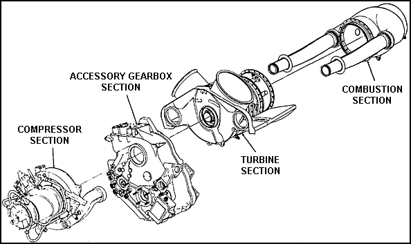
Figure 7.1. Sections of the T63 Engine.
7.2. OPERATIONAL DESCRIPTION
The T63 turboshaft engine, being an internal combustion engine, requires intake, compression, combustion, and exhaust, as does a reciprocating engine.
Figure 7.2 is a cutaway view of the T63 engine. By looking at the letters in the arrows in figure 7.2, you will be able to follow the air's path through the engine.
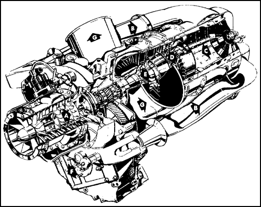
Figure 7.2. Airflow Diagram.
Air is routed to the compressor assembly by intake ducts on the aircraft. The (A) compressor assembly "squeezes" incoming air to high pressures. This compressed air is discharged through twin air-transfer tubes (B) into the combustion chamber (C) and mixed with fuel which is then burned. The exhaust gases expand through the compressor turbine (D) which extracts energy from these hot gases to drive the compressor (A). The power turbine (E) takes the remaining energy to drive the power-output shaft (F). The gases are then released through exhaust ducts (G).
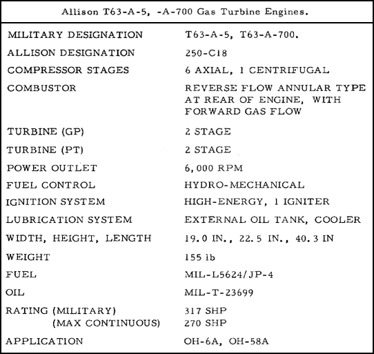
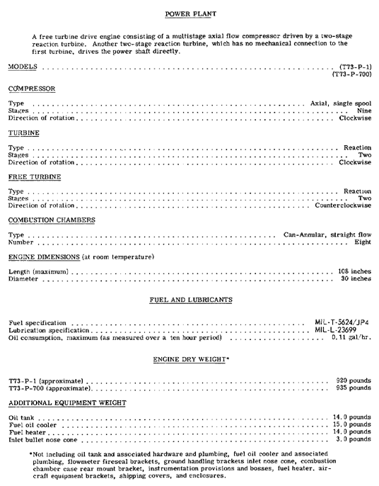
7.3. ALLISON T63 SPECIFICATIONS
Specifications for the T63-A-5A and 700 engines used in Army aircraft are summarized in the following chart.
The compressor assembly consists of the following: compressor front support, compressor case, diffuser scroll, front diffuser, rear diffuser, rotor, rotor bearing, and oil seals. An exploded view of the compressor assembly is shown in figure 7.3.
The compressor is a combination axial-centrifugal type with six stages of axial compression and one stage of centrifugal compression. The rotor hub and blade assemblies and the impeller are made from stainless steel. The compressor rotor front bearing (No. 1) is housed in the compressor front support, and the compressor rotor rear (No. 2) bearing is housed in the compressor rear diffuser. The No. 2 bearing is the thrust bearing for the compressor rotor assembly.
The compressor case assembly consists of upper and lower halves and is made of stainless steel. Thermal-setting plastic is centrifugally cast to the inside surface of the case halves and vane outer bands.
To achieve maximum compressor efficiency, a minimum clearance is necessary between the compressor-blade tips and the case. The first time an engine is started, the blade tips cut their own tip clearance in the plastic coating. The inside of the compressor must be kept free of dirt accumulation. A dirty compressor can cause high turbine outlet temperatures, low engine power, and eventual engine failure. Engine cleaning procedures can be found in the appropriate aircraft or engine maintenance manual. The compressor of the T63 must never be cleaned with an ordinary cleaning solvent, because this will dissolve the plastic coating on the inside of the compressor case and cause engine failure.
A control valve is mounted on the compressor case assembly to bleed air off the 5th stage of the compressor during starting and all engine operations at low pressure ratios.
The compressor diffuser assembly consists of stainless steel front and rear diffusers and a magnesium alloy scroll. The scroll collects the air and delivers it to two elbows. Compressor-discharge air tubes deliver compressed air from the outlet of the elbows to the combustion outer case. The diffuser scroll has five ports from which air can be bled or compressor discharge air pressure sensed. Two of these ports are customer bleed air ports, and the remaining ports are used by the anti-icing valve, fuel control pressure sensing, and bleed air pressure sensing. Customer air ports are used by the airframe manufacturer to tap bleed air to run pumps, heaters, and so forth.
7.5. ACCESSORY GEARBOX SECTION
Shown in figure 7.4, the accessory gearbox is the primary structural member of the engine. All engine components, including the engine mounted accessories, are attached to the case, which has four mounting pads, one on each side, one on the top, and one on the bottom. The side pads must be used, and the helicopter manufacturer has his choice of using the top and bottom pads. The accessory gearbox contains most of the lubrication system components and houses the power turbine and gas producer gear trains. The power turbine gear train, shown in figure 7.5, reduces engine N2 speed from 35,000 to 6,000 rpm. The power turbine gear train drives the torquemeter, N2 tachometer-generator, and N2 governor. The gas producer gear train, illustrated in figure 7.6, drives the oil pumps, fuel pump, gas producer fuel control, N1 tachometer generator, and starter-generator. During starting, the starter-generator cranks the engine through the gas producer gear train.
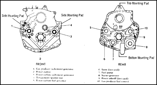
Figure 7.4. Accessory Gearbox Case.
7.6. TURBINE SECTION
As shown in figure 7.1, the turbine section is mounted between the combustion section and the power and accessory gearbox. The turbine section consists of a two-stage gas producer turbine, shown in figure 7.7, and a two-stage power turbine, shown in figure 7.8. Power to drive the compressor rotor is furnished by the gas producer turbine rotor through a direct drive. The power turbine rotor converts the remaining gas energy into power which drives the power output shaft. The exhaust gases are directed into the exhaust collector support and through the twin exhaust ducts on the top of engine.
The gas producer turbine nozzles (1st and 2nd) are housed in the gas producer turbine support. The power turbine (3rd and 4th stage) nozzles are housed in the power turbine support and the aft end of the exhaust collector support. These nozzles may be seen by looking at figures 7.7 and 7.8. These nozzles increase the velocity of the expanding gas and direct the gas at the proper angle onto the turbine rotors.
The oil system is a circulating dry-sump type with an external oil tank and cooler. The engine oil-system schematic is illustrated in figure 7.9. This system is designed to supply oil for lubrication, scavenging, and cooling as needed.
Spray jet lubrication is used on all compressor, gas producer turbine, and power turbine rotor bearings, and to bearings and gear meshes of the power turbine gear train, with the exception of the power output shaft bearings. The power output shaft bearings and all other gears and bearings are lubricated by oil mist.
A spur-gear oil pump assembly, illustrated in figure 7.10, consisting of one pressure element and four scavenge elements, is mounted within the accessory gearbox.
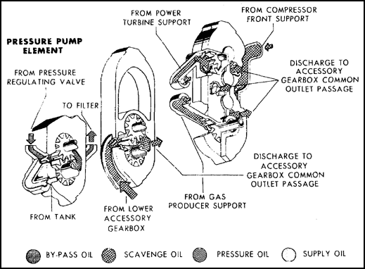
Figure 7.10. Oil Pump.
The oil filter assembly, located in the upper right-hand side of the accessory gearbox, consists of a filter bypass valve and a pressure regulating valve. Oil from the tank is delivered to the pressure pump which pumps oil through the filter and then to the points of lubrication. The oil pressure is regulated 115-130 psi by the pressure regulating valve.
The engine lubrication system incorporates four screens, two magnetic chip detector plugs, and two check valves. The check valve in the oil filter outlet passage prevents oil in the tank from draining into the engine when it is not in operation.
To further prevent internal oil leakage at engine shutdown, an external sump is connected to the scavenge oil line at the power turbine support. One magnetic chip detector plug is in the accessory gearbox sump, and the other one is in the scavenge oil pressure line which delivers oil to the oil outlet port on the gearbox.
7.8. TORQUEMETER
A torquemeter is located on the instrument panel and is connected to a transmitter which is part of the engine oil system. The torque indicating system converts the pressure sensed at the torquemeter pressure port, on the front side of the accessory gearbox, into an indication in psi of engine torque output.
7.9. FUEL CONTROL SYSTEM
The fuel control system meters fuel during starting, acceleration, constant speed, and deceleration. This control system consists of governor, accumulator and check valve, and fuel nozzle. These components are illustrated in figure 7.11. The following subparagraphs cover each component in the fuel system.
![]() a. The fuel pump assembly consists of two spur-gear pumps, filter, filter bypass valve, regulator valve, and two discharge check valves. As shown in figure 7.12, the fuel pumps are parallel, that is, fuel entering the inlet port can be pumped by either pump to the outlet port. Each pump has a separate shear point. In the event of a pump failure, the discharge check valve of the failed pump closes to prevent reverse flow through the pump. Failure of one pump will not affect engine operation.
a. The fuel pump assembly consists of two spur-gear pumps, filter, filter bypass valve, regulator valve, and two discharge check valves. As shown in figure 7.12, the fuel pumps are parallel, that is, fuel entering the inlet port can be pumped by either pump to the outlet port. Each pump has a separate shear point. In the event of a pump failure, the discharge check valve of the failed pump closes to prevent reverse flow through the pump. Failure of one pump will not affect engine operation.
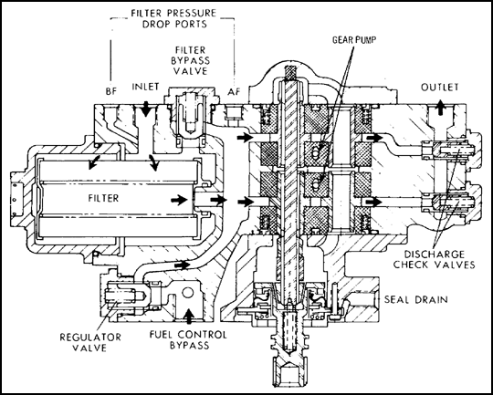
Figure 7.12. Fuel Pump and Filter Assembly.
![]() b. The fuel control (N1) is located at the 3 o'clock position on the accessory gearbox case. The fuel control delivers metered fuel (P2 in figure 7.11) to the fuel nozzle. The gas producer fuel control, driven by the N1 gear train, senses compressor discharge pressure (PC). The N1 fuel control lever, positioned by the twist grip throttle, is mechanically linked to a pointer and the fuel cutoff valve. A quadrant, shown in figure 7.13, with 0, 5, 30, and 90 degree indications is located adjacent to the pointer. The pilot's twist grip throttle has three basic positions: cutoff is 00 to 50; ground idle is at 300, and full open at 900. When the twist grip is moved from cutoff to ground idle during engine start, the fuel control automatically meters fuel in response to N1 rpm. The engine starts, accelerates, and stabilizes at ground idle rpm. Fuel flow during this phase is metered entirely by the fuel control.
b. The fuel control (N1) is located at the 3 o'clock position on the accessory gearbox case. The fuel control delivers metered fuel (P2 in figure 7.11) to the fuel nozzle. The gas producer fuel control, driven by the N1 gear train, senses compressor discharge pressure (PC). The N1 fuel control lever, positioned by the twist grip throttle, is mechanically linked to a pointer and the fuel cutoff valve. A quadrant, shown in figure 7.13, with 0, 5, 30, and 90 degree indications is located adjacent to the pointer. The pilot's twist grip throttle has three basic positions: cutoff is 00 to 50; ground idle is at 300, and full open at 900. When the twist grip is moved from cutoff to ground idle during engine start, the fuel control automatically meters fuel in response to N1 rpm. The engine starts, accelerates, and stabilizes at ground idle rpm. Fuel flow during this phase is metered entirely by the fuel control.
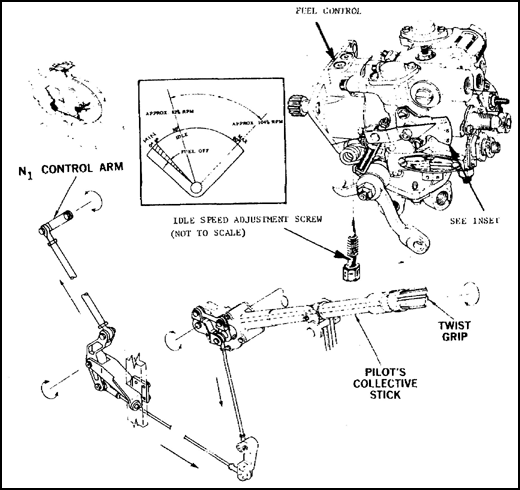
Figure 7.13. Fuel Control System.
![]() c. The power-turbine governor (N2) is not required for starting or ground idle operation,but it is required for speed governing of the power turbine rotor. The gas-producer fuel control and the power-turbine governor are connected together by two pneumatic lines, labeled PG and PR in figure 7.11. The power-turbine governor, driven by the power-turbine gear train, senses compressor discharge pressure (PC). The power-turbine governor lever, as shown in figure 7.14, is positioned by the helicopter droop compensator or the N2 actuator. The power-turbine governor is required for speed governing of the power turbine rotor (N2). The N2 rpm at which the power-turbine governor will govern is under the control of the N2 actuator. Normally, the power-turbine governor is operated at 100 percent N2. However, the pilot can select a setting of the governor either higher or lower than 100 percent N2.
c. The power-turbine governor (N2) is not required for starting or ground idle operation,but it is required for speed governing of the power turbine rotor. The gas-producer fuel control and the power-turbine governor are connected together by two pneumatic lines, labeled PG and PR in figure 7.11. The power-turbine governor, driven by the power-turbine gear train, senses compressor discharge pressure (PC). The power-turbine governor lever, as shown in figure 7.14, is positioned by the helicopter droop compensator or the N2 actuator. The power-turbine governor is required for speed governing of the power turbine rotor (N2). The N2 rpm at which the power-turbine governor will govern is under the control of the N2 actuator. Normally, the power-turbine governor is operated at 100 percent N2. However, the pilot can select a setting of the governor either higher or lower than 100 percent N2.
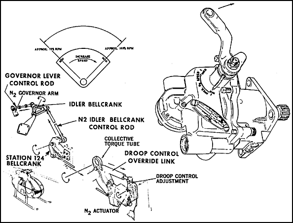
Figure 7.14. Power Turbine Governor Control System.
The droop compensator moves the governor Lever any time the pilot's collective stick is increased or decreased. This is necessary to maintain the N2 rpm the pilot has set with the N2 actuator. When collective pitch is increased, the power requirements are increased, and N2 rpm droops slightly. The governor senses the N2 droop and it signals the gas-producer fuel control to meter more fuel. As fuel flow increases, N2 returns to the setting of the power-turbine governor. When collective pitch is decreased, the power requirements are decreased, and N2 increases slightly. The governor senses the N2 increase and signals the fuel control to meter less fuel. As fuel flow decreases, the N2 decreases to the setting of the power-turbine governor.
![]() d. The check valve assembly and accumulator are installed to dampen torsional vibrations encountered in helicopter rotor systems. Because of wind gusts and turbulent air conditions, the rotor rpm will fluctuate slightly. The power turbine governor senses this rpm change and causes the fuel control to vary fuel flow. By installing an accumulator and damping out the governing pressure (PG) to the gas producer fuel control, the design prevents the engine from responding to torsional vibrations.
d. The check valve assembly and accumulator are installed to dampen torsional vibrations encountered in helicopter rotor systems. Because of wind gusts and turbulent air conditions, the rotor rpm will fluctuate slightly. The power turbine governor senses this rpm change and causes the fuel control to vary fuel flow. By installing an accumulator and damping out the governing pressure (PG) to the gas producer fuel control, the design prevents the engine from responding to torsional vibrations.
![]() e. The fuel nozzle is a single-entry, dual-orifice type nozzle. It threads into the combustor outer case and extends into the aft end of the combustor liner. The fuel control delivers fuel to the nozzle which atomizes and injects fuel into the combustion chamber, where it is mixed with air and burned.
e. The fuel nozzle is a single-entry, dual-orifice type nozzle. It threads into the combustor outer case and extends into the aft end of the combustor liner. The fuel control delivers fuel to the nozzle which atomizes and injects fuel into the combustion chamber, where it is mixed with air and burned.
The fuel nozzle must properly atomize and inject the fuel in all ranges of fuel flow from starting to maximum power. This is accomplished by means of a dual-orifice design. The primary orifice has fuel delivered to it whenever the engine is operating, but the secondary orifice receives fuel only when the fuel pressure to the fuel nozzle exceeds 150 psi.
7.10. AIR BLEED AND ANTI-ICING SYSTEMS
The compressor air bleed system permits rapid engine response by relieving compressor pressure during engine acceleration. A bleed air control valve is mounted to the bleed air manifold on the compressor case. The compressor bleed air and anti-icing systems are illustrated in figure 7.15.
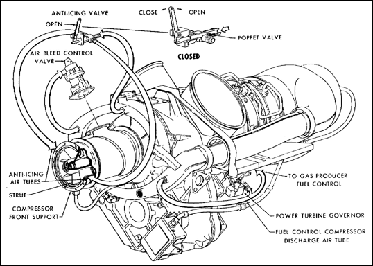
Figure 7.15. Air Bleed and Anti-Icing System.
Elongated slots between every other vane at the compressor fifth stage bleed compressor air into a manifold on the compressor case. The air bleed control valve is open during starting and ground-idle operation, and it remains open until a predetermined pressure ratio is obtained, at which time the valve begins to move from the open to the closed position.
The engine is equipped with an anti-icing system that conducts hot air to the compressor front-support struts to prevent ice forming on the struts. The system is entirely separate and independent of any other bleed air system. The engine anti-icing system must be turned on by the pilot. As air passes through the compressor, it is compressed. As a result of this compression, the air is heated and is a source of hot air required by the engine anti-icing system.
The anti-icing system consists of an anti-icing valve, two tubes, and passages within the compressor front support. During operation of the system, the anti-icing tubes deliver hot air from the anti-icing valve to the two ports on the compressor front support. These ports deliver the hot air into an annular passage formed between the dual-walled housing. Hot air flows from the annular passage through the hollow inlet guide vanes into the front bearing support hub. Some of the air flowing through the struts is exhausted out of slots on the trailing edge of the guide vanes, and the remaining air is exhausted out of holes in the front bearing support hub. During anti-icing operation, all surfaces of the compressor front support which come in contact with compressor inlet air are heated and ice cannot form.
7.11. IGNITION AND TURBINE OUTLET TEMPERATURE MEASUREMENT SYSTEMS
The ignition system is composed of three components: a low-tension capacitor exciter-assembly, a spark igniter lead, and a shunted surface gap spark igniter. The system is powered by the aircraft 28-volt dc electrical system. This ignition system is only required during starting, because continuous combustion takes place after the engine is started. Components of the ignition and turbine outlet temperature (TOT) systems are illustrated in figure 7.16.
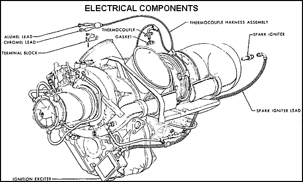
Figure 7.16. Electrical Components.
The TOT thermocouple harness contains four probes used to sense the temperature of the gases on the outlet side of the gas-producer turbine rotor. Each thermocouple probe generates a dc millivoltage which is directly proportional to the gas temperature it senses. The thermocouple harness averages the four voltages produced and indicates TOT on a gage in the cockpit.
7.12. SUMMARY
The Allison T63 is a free-power gas turbine engine which has four major sections: the compressor assembly,power and accessory gearbox, turbine assembly, and combustion assembly. The power-turbine governor senses power turbine speed and relays this to the fuel control that controls the compressor speed. The fuel control sends fuel to the nozzle located in the combustion section, and the nozzle sprays fuel into the combustion liner.
The engine is lubricated by a dry-sump pressure system. Ignition for engine starting comes from an ignition exciter and spark igniter located next to the fuel nozzle in the engine combustion section.
Chapter 8
PRATT AND WHITNEY T73
8.1. INTRODUCTION
The Pratt and Whitney T73-P-1 and T73-P-700 are the most powerful engines used in Army aircraft. Two of these engines are used to power the CH-54 flying crane helicopter. The T73 design differs in two ways from any of the engines covered previously. The airflow is axial through the engine; it does not make any reversing turns as the airflow of the previous engines did, and the power output shaft extends from the exhaust end.
Chapter 8 describes and discusses the engine sections and systems. Constant reference to the illustrations in this chapter will help you understand the discussion.
8.2. GENERAL DESCRIPTION
The T73-P-1 and the T73-P-700 engines are straight-flow, free-turbine power plants using a two-stage turbine to drive a nine-stage, axial-flow compressor. The free turbine uses the exhaust gas to drive a two-stage free turbine rotor. External views of the T73 gas turbine engine are shown in figure 8.1. A cross-sectional view is shown in figure 8.2.
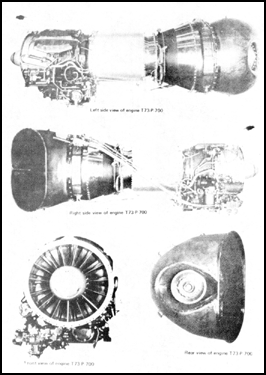
Figure 8-1. T73-P-700 Gas Turbine Engine.
The axial flow compressor consists of a nine-stage rotor and nine stator stages. The gas path of the compressor is so designed that it forms a convergent duct. The compressor has a moderate compression ratio.
An automatically-controlled interstage airbleed is used for starting and low power operation of the engine. The engine's anti-icing system prevents dangerous accumulations of ice on compressor-inlet surfaces by directing compressor-discharge air into the hollow compressor inlet guide vanes.
To the rear of the compressor is the diffuser section which reduces air velocity and increases air pressure for entry into the combustion chambers.
The combustion section houses the canannular combustion chambers and the fuel. manifolds. The eight separate combustion chambers, arranged annularly, are connected by flame tubes.
Igniter plugs are installed in number three and six combustion chambers. Right and left, clockwise and counterclockwise, upper and lower, and similar directional references apply to the engine as viewed from the rear, with the accessory section at the bottom. Table V gives the leading particulars for the T73-P-700 and T73-P-1 engines.
TABLE V. LEADING ENGINE PARTICULARS
The compressor inlet case, illustrated in figure 8.3, consists of the outer and inner inlet cases, outer and inner inlet vane shrouds, and hollow inlet vanes. Bosses and pads are located on the outer case for the No. 1 bearing compartment breather, scavenge, and pressure connections, inlet air pressure and temperature sensing connections, and anti-icing a air-icing air ports. The No. 1 bearing housing is bolted to the inner-inlet-case rear flange.
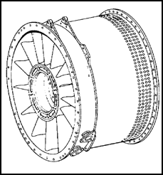
Figure 8.3. Compressor Inlet Case.
The compressor inlet case houses the first four compressor rotor and compressor vane and shroud stages. Ports in the rear of the case allow bleed air to be discharged overboard by a bleed band assembly to aid engine starting and acceleration.
The compressor rotor, shown in figure 8.4, consists of a forward hub assembly, a nine-stage compressor rotor, and an aft hub assembly. The No. 1 bearing is installed on the forward hub assembly of the compressor rotor shaft.
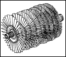
Figure 8.4. Compressor Rotor.
The first stage compressor blades are attached directly to the forward hub while all other stages of compressor blades are attached to individual disks. The blades of the first and second stages are pin mounted to allow the blades to flex. Stages three through nine have a single dovetail and are secured in broached slots in the disk by expend able blade locks.
The diffuser case, illustrated in figure 8.5, is a welded steel assembly located between the compressor inlet case and the combustion chamber case. It consists of an inner and outer case and 8 hollow struts. It houses stages 5 through 9 of the compressor rotor shroud and vane assembly, the 9th stage exit guide vanes, and No. 2 main bearing and seal.
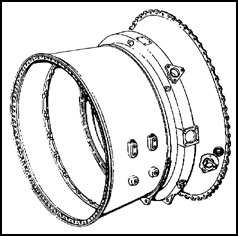
Figure 8.5. Diffuser Case.
The diffuser assembly reduces air velocity and increases air pressure for entry into the combustion chambers. High pressure air from this case is bled off for anti-icing, fuel heating, and bearing pressurizing.
On the outer case at the 3 and 9 o'clock positions are the engine mount pads. At the bottom of the case are bosses for installing the gearbox and the fuel-pressurizing dump valve.
The combustion chamber case is bolted between the diffuser case and the free turbine case. This combustion chamber outer case, shown in figure 8.6, forms the outer rigid support member of theengine and must be removed for completing a hot section inspection. Located within the combustion outer case are eight combustion chambers (cans), the combustion inner case, fuel manifolds, and the combustion chamber outlet duct. The combustion chambers are attached by clamps to the combustion chamber outlet duct in the aft end of the combustion chamber case. Flame tubes interconnect all combustion chambers. Chambers three and six have igniter plug cutouts. Each combustion chamber, illustrated in figure 8.7, consists of six liners, a fuel nozzle cap, a fuel nozzle cup adapter, and male or female flame tubes.
Figure 8.6. Combustion Chamber Case.
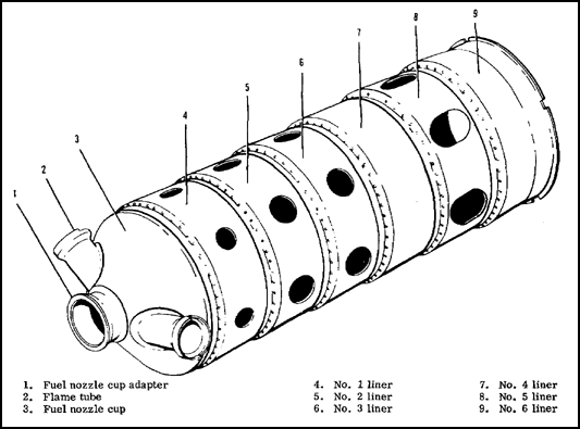
Figure 8.7. Combustion Chamber.
The combustion chamber outlet duct, shown in figure 8.8, acts as a transition area to combine the gas flow from the eight combustion chambers and introduce it into the first stage nozzle vanes.
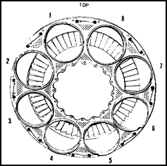
Figure 8.8. Combustion Chamber Outlet Duct and Combustor (Can) Positions.
The fuel manifold consists of a secondary manifold within the primary manifold. Eight duplex fuel nozzles, one for each combustion chamber, are placed around the fuel manifold. Each nozzle has a primary orifice and a secondary orifice. Fuel sprays from the primary orifice during low pressure and from both orifices at high pressure. Fuel strainers in the primary and secondary passages of each nozzle prevent foreign matter from clogging the orifices. A fuel drain valve, at the bottom of the combustion case, automatically drains the combustion section after engine shutdown in the event of a false or aborted start.
8.5. GAS PRODUCER TURBINE SECTION
The gas producer turbine rotor assembly, illustrated in figure 8.9, consists of the turbine shaft and the first and second stage disks and blades. The turbine disks are attached to the turbine shaft hub with bolts and are separated from each other by the turbine rotor inner seal. The first and second stage turbine blades are shrouded. The shrouds form a continuous band which tends to reduce blade vibration, improve the airflow characteristics, and increase the efficiency of the turbine. The first and second stage turbine blades are placed in the fir-tree serrations of the disks and are held in place with rivets.
Figure 8.9. Gas Producer Turbine Rotor.
The turbine rotor is supported by the No. 3 bearing and by the splined end of the compressor rear hub. Installed on the turbine shaft is the No. 3 bearing seal assembly.
8.6. POWER TURBINE SECTION
The free-power turbine is a two-stage axial-flow turbine. The turbine inlet case, item 25, figure 8.2, is mounted on the rear flange of the gas producer turbine case. The power-turbine rotor turns counterclockwise while the gas producer rotor turns clockwise. The power turbine rotor assembly, items 16 and 18 in figure 8.2, consists of the turbine shaft, first and second stage disk and blades, turbine coupling, and accessory drive gear. Tiebolts attach the disk and blade assemblies to the front end of the turbine shaft. The shaft is supported at the rear by the No. 5 bearing and at the forward end by the No. 4 bearing.
The free-turbine inlet case houses the turbine inlet duct, the first and second stage vanes, and the free-stage turbine rotor.
The free-turbine case, item 24, figure 8.2, is mounted to the rear flange of the free turbine inlet case. The turbine case consists of the free-turbine outer case, inner front and rear case, four hollow struts and their Outer shrouds, twelve exhaust struts, and the No. 4 bearing housing. Housed in the case are the free-power turbine second-stage rotor, No. 4 bearing oil nozzle, and free turbine accessory drive gear and shaft assembly, item 20 in figure 8.2.
8.7. TURBINE EXHAUST DUCT
The free-turbine shaft and shaft cases are housed in the exhaust duct. The exhaust duct assembly consists of inner and outer assemblies, stiffeners, exhaust duct ring, and front and rear flanges. The exhaust duct bolts to the free-turbine case rear flange.
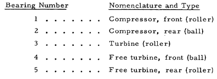
8.8. MAIN BEARINGS
All references to main bearings in this chapter are made by bearing number rather than by bearing nomenclature. Here are the bearing numbers with their corresponding nomenclatures and types.
The T-73 is equipped with a single-element, centrifugal-boost fuel pump. The pump is mounted on and driven by the component-drive gearbox. On the rear of the pump is a mounting pad for the engine fuel control. The fuel boost pump raises the fuel pressure by approximately 20 psi. Fuel then passes through an externally mounted fuel de-icing heater. From the de-icing heater, fuel returns to the pumps at the inlet fuel filter and is directed to the main pumping element. The main pumping element raises the pressure to approximately 800 psi, and fuel passes out of the pump to the engine fuel control.
The fuel control is a hydromechanical control designed to meter fuel to the engine. The control has a fuel metering system and a computing system. The metering system, subject to engine operating limitations, selects the rate of fuel flow supplied to the engine in accordance with the amount of power requested. The computing system allows the maximum engine performance available without exceeding operating limits. The fuel then flows through tubing to the right and left fuel manifolds and the eight fuel nozzles in the combustors.
8.10. INTERNAL COOLING AND PRESSURIZATION
Ninth stage air passes through holes in the compressor rotor rear hub, down through the inside of the rotor, and out through holes in the front hub. This air is used to pressurize the main bearing seals and to cool hot parts of the engine.
8.11. INLET GUIDE VANE ANTI-ICING SYSTEM
To prevent icing of the compressor inlet surfaces, an anti-icing air system is installed in the engine. Compressor bleed air is carried forward to the inlet case by an external tube on the left side of the engine. Air flow through this tube is controlled by a solenoid-operated valve. When icing conditions are encountered, the anti-ice switch in the cockpit is turned on to deenergize the solenoid which allows the valve to open and hot anti-icing air to pass forward.
Anti-icing air enters the compressor inlet outer case through the anti-icing air boss and into the cavity formed by the compressor-inlet outer case and the IGV outer, shroud. The air then passes through the hollow inlet-vanes and through openings in the inner shroud to the bullet nose cone.
The air passes through the bullet nose cone and is ejected out through louvers into the air-stream.
The engine lubrication system is illustrated in figure 8.10. Oil from the tank is fed to the inlet of the pressure section of the main oil pump. The pressure oil is then directed through the main oil filter, through the fuel oil cooler if cooling is required, and to the bearings. The oil passes through external tubing to the No. 1 and 2 bearing compartments. Oil to the No. 3 bearing compartment is supplied by an internal tube that connects with No. 2 bearing supply. Pressure oil flows through an external tube to the free turbine accessory drive gearbox. An internal line carries oil from this connector to the No. 4 and 5 bearings. Pressure oil flow is maintained by metering orifices, thus providing a relatively constant oil flow at all engine operating speeds. Oil pressure is controlled by the pressure relief valve. If the oil strainer becomes clogged, a bypass valve opens permitting oil flow and allowing engine operation to continue.
Scavenge oil from the five main bearings and gearbox is scavenged by five of the six gear stages in the main oil pump.
The first stage is a pressure pump. Stage two scavenges oil from No. 1 bearing; stage three from No. 3 bearing; stage four from the gearbox and No. 2 bearing; stage five from No. 4 bearing; and stage six from No. 5 bearing. The scavenge oil empties into a common tube that returns the oil to the tank. An air-oil separator in the gearbox removes oil from the breather air. Return oil passes through a de-aerator which removes most of the air. The oil tank contains baffles to prevent re-aeration of the oil in the tank.
Each of the bearing compartments and the oil tank are vented to the components drive gearbox. A rotary separator within the gearbox separates the majority of oil particles from the breather air. This air then exits through the overboard breather connector on the upper right side of the gearbox.
The torque sensor, the ignition system, and the power turbine inlet temperature indicating system make up the engine electrical system.
The torque sensor consists of a torque shaft assembly, a three-pole magnetic torque sensor, and a torquemeter. It produces a visual indication of power transmitted from the engine to the main rotor gearbox by measuring the main drive shaft twist resulting from engine torque.
8.14. IGNITION SYSTEM
The ignition circuit is energized only during the starting cycle through operation of the starter circuit. The ignition system components consists of two identical, four-joule ignition exciters, one for each igniter plug. The ignition system operates satisfactorily with an input voltage of 14 to 30v dc. Operation of this system is the same as described in lesson 3, paragraph 2.22.
8.15. POWER TURBINE INLET TEMPERATURE INDICATING SYSTEM
This system consists of a dual-junction thermocouple cable and six thermocouples. Two connectors are provided in the thermocouple cable illustrated in figure 8.11. One is for connecting to an averaging indicator and the other is for individual checking of the thermocouples. This system functions the same as the exhaust gas temperature-measuring system described in lesson 3.
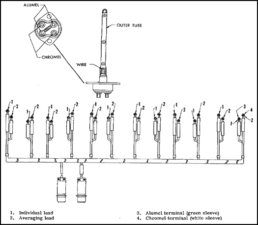
Figure 8.11. Dual-Junction Thermocouple and Harness.
The Pratt and Whitney T73-P-1 and the T73-P-700 are used to power the CH-54 flying crane helicopter. This engine is a straight-flow, axial-compressor,free-turbine powerplant. The axial flow compressor consists of nine stages. The combustion section has eight separate combustion chambers. The compressor is driven by a two-stage turbine mounted on the aft end of the compressor rotor shaft.
The power turbine section is also a two-stage turbine, which mounts on the front end of the turbine shaft. The turbine shaft extends out the exhaust end of the engine.
The engine fuel system has a hydromechanical fuel control with a metering and computing section that schedules fuel flow. Internal cooling and pressurization are maintained by compressor bleed air. Compressor bleed air is also used to prevent ice from forming on the engine inlet surfaces. All components of the lubrication system are mounted on the engine. The oil system is a dry-sump type.
The engine electrical system consists of the torque sensing system, ignition system, and turbine inlet temperature system.
Chapter 9
PRATT AND WHITNEY T74
This chapter discusses the Pratt and Whitney T74 gas turbine engine. It is a reverse-flow,free-power turbine engine using a combination axial-centrifugal compressor assembly. The two models of the T74 are the T74-CP-700 and the T74-CP-702. They are used on the U-21 aircraft. Information in this chapter may be about either or both models.
Section I describes the engine operation, and section II discusses the major engine systems. Figure 9.1 shows what the engine looks like; in this case, it is the -700 model.
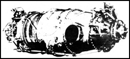
Figure 9.1. T74-CP-700.
Section I. Operational Characteristics and Description
9.2. GENERAL
This section discusses the operational characteristics and gives a description of the T74 engine. However, because these engines are undergoing continuous improvements in design and manufacture, the appearance of certain parts or details may change.
9.3. OPERATING CHARACTERISTICS
A cross-sectional view of the T74 showing the airflow through the engine is illustrated in figure 9.2. Inlet air enters the engine through a circular chamber formed by the compressor inlet case where it is directed to the compressor. The compressor consists of three axial stages combined with a single centrifugal stage.
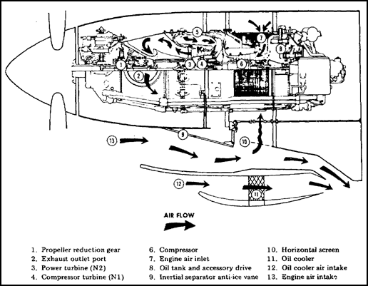
Figure 9.2. Airflow.
A row of stator vanes, located behind each rotating disk, diffuses the air, raises its static pressure, and directs it to the next stage of compression. The compressed air passes through a diffuser, turns ninety degrees in direction, and is then led through straightening vanes into the combustion chamber liner.
The annular combustion chamber liner (ring shaped) has perforations which allow entry of compressed air. The flow of air changes direction to enter the combustion chamber liner, where it reverses direction and mixes with fuel. The location and shape of the combustion chamber liner eliminates the need for a long shaft between the compressor and turbine, reducing the overall length and weight of the engine.
Fuel is injected into the combustion chamber liner by fourteen simplex nozzles. The fuel-air mixture is ignited by two glow plugs which protrude into the combustion chamber liner. The expanding gas from the combustion chamber liner reverses direction and passes through the compressor turbine guide vanes to the compressor turbine. The gases then pass forward through the turbine guide vanes to drive the power turbine.
The compressor and power turbines, items 3 and 4 in figure 9.2, are located approximately in the center of the engine with their shafts extending in opposite directions. The exhaust gas from the power turbine is directed through an exhaust plenum to two exhaust ducts.
All engine-driven accessories, with the exception of the N2 tachometer-generator and propeller governors, are mounted on the accessory gearbox and driven by the compressor. The oil tank is located forward of the accessory gearbox and forms part of the compressor inlet case. The tank has a total oil capacity of 2.3 gallons and has a dipstick and drain plug.
The power turbine drives a propeller through a two-stage planetary reduction gearbox located at the front of the engine. The torquemeter is located in the reduction gearbox.
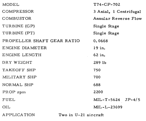
9.4. STATIONS, FLANGES, AND SPECIFICATIONS
The engine stations and flanges are illustrated in figure 9.3. Stations, identified by numbers in the figure, are specific locations in the engine. Flanges, identified by letters in the figure, are rims or edges providing strength in the attachment of one engine section to another.
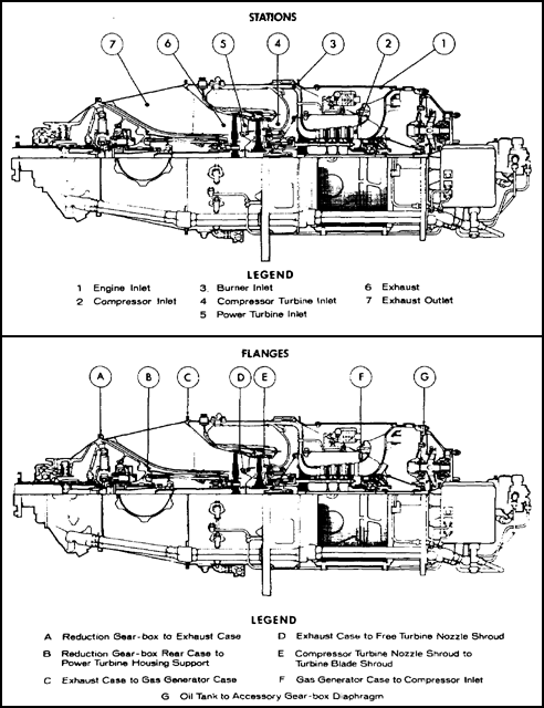
Figure 9.3. Stations and Flange Locations, -700.
Specifications for the T74-CP-702 engines used in Army aircraft are summarized in the following chart.
9.5. INLET AND COMPRESSOR SECTIONS
The following subparagraphs discuss the inlet and compressor sections. An exploded view of the T74-CP-702 engine is shown in figure 9.4.
![]() a. The compressor inlet case, shown in figure 9.5, consists of a circular aluminum-alloy casting; the front forms a plenum chamber for the passage of compressor inlet air. The rear portion, which consists of a hollow compartment, is used to house the oil supply. A large circular steel screen (item 11 in figure 9.4) is bolted around the air intake and the rear of the gas generator case to prevent foreign object ingestion by the compressor.
a. The compressor inlet case, shown in figure 9.5, consists of a circular aluminum-alloy casting; the front forms a plenum chamber for the passage of compressor inlet air. The rear portion, which consists of a hollow compartment, is used to house the oil supply. A large circular steel screen (item 11 in figure 9.4) is bolted around the air intake and the rear of the gas generator case to prevent foreign object ingestion by the compressor.
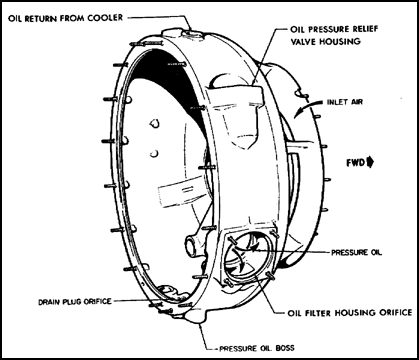
Figure 9.5. Compressor Inlet Case, -700 Engine.
The No. 1 bearing support is contained within the compressor inlet case centerbore. A conical tube is fitted in the centerbore of the oil tank compartment to provide a passage for the coupling shaft which extends the compressor drive to the accessories mounted on the rear accessory case. The pressure oil pump, driven by an accessory drive gear, is located in the bottom of the oil tank. The pressure oil relief valve and main oil filter, with check valve and bypass valve assemblies; are located on the right side of the inlet case at the 1 and 3 o'clock positions, respectively.
![]() b. The compressor rotor and stator assembly, shown in figure 9.6, consists of a three-stage axial rotor, three interstage spacers, three stator assemblies, and a single-stage centrifugal impeller and housing. The compressor blades are made of stainless steel and attached, with limited clearance, to the compressor hub in dovetail grooves. This accounts for the metallic clicking heard during compressor run-down. Axial movement of compressor blades is limited by the interstage spacers located between the disks. The first stage compressor blade airfoil differs from those in the second and third stages which are identical. All three stages differ in length, decreasing from the first to the third stage. The No. 1 bearing is a ball bearing and supports the rear of the compressor assembly in the inlet case. The No. 2 bearing is a roller bearing and supports the front of the compressor and gas generator turbine.
b. The compressor rotor and stator assembly, shown in figure 9.6, consists of a three-stage axial rotor, three interstage spacers, three stator assemblies, and a single-stage centrifugal impeller and housing. The compressor blades are made of stainless steel and attached, with limited clearance, to the compressor hub in dovetail grooves. This accounts for the metallic clicking heard during compressor run-down. Axial movement of compressor blades is limited by the interstage spacers located between the disks. The first stage compressor blade airfoil differs from those in the second and third stages which are identical. All three stages differ in length, decreasing from the first to the third stage. The No. 1 bearing is a ball bearing and supports the rear of the compressor assembly in the inlet case. The No. 2 bearing is a roller bearing and supports the front of the compressor and gas generator turbine.
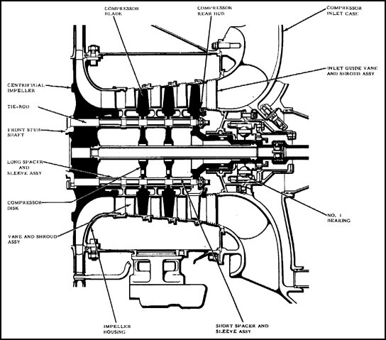
Figure 9.6. Compressor Assembly, -700.
![]() c. The gas generator case is attached to the front flange of the compressor inlet case and consists of two stainless steel sections made into a single structure. The rear inner section supports the compressor assembly. The compressor bleed valve outlet port is located at the seven o'clock position forward of the inlet screen. The No. 2 bearing support is located in the centerbore of the case. The diffuser pipes or vanes brazed inside the center section of the gas generator case create a pressure increase in the compressor air as it leaves the centrifugal impeller. The compressed air is then directed through straightening vanes, located at the outlet of the diffuser, and out to the combustion chamber liner.
c. The gas generator case is attached to the front flange of the compressor inlet case and consists of two stainless steel sections made into a single structure. The rear inner section supports the compressor assembly. The compressor bleed valve outlet port is located at the seven o'clock position forward of the inlet screen. The No. 2 bearing support is located in the centerbore of the case. The diffuser pipes or vanes brazed inside the center section of the gas generator case create a pressure increase in the compressor air as it leaves the centrifugal impeller. The compressed air is then directed through straightening vanes, located at the outlet of the diffuser, and out to the combustion chamber liner.
The front section of the gas generator case forms the outer housing for the combustion chamber liner. It consists of a circular stainless steel structure for mounting the 14 fuel nozzle assemblies and the manifold. Front and rear drain valves are mounted at the 6 o'clock position to allow residual fuel to drain overboard during engine shutdown after a false or aborted start. Two glow plugs protrude into the combustion chamber liner to ignite the fuel-air mixture. The engine is mounted on three flexible type mounts which are secured to mounting pads located on the outer circumference of the gas generator case.
9.6. COMBUSTION CHAMBER LINER
Located in the front section of the gas generator case is the combustion chamber liner. The liner is of the reverse flow type and consists primarily of an annular, heat-resistant steel liner open at one end. The combustion chamber is illustrated in figure 9.7.
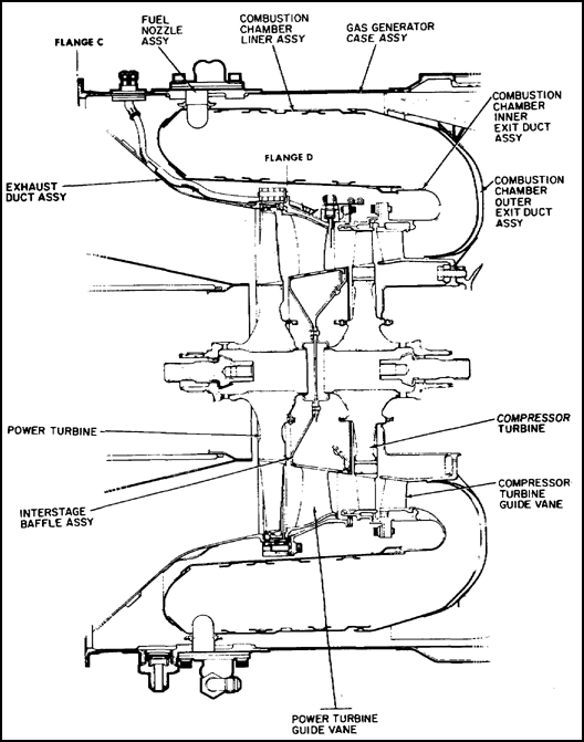
Figure 9.7. Combustion Chamber and Turbine Section, -702.
The liner has perforations which allow air to enter the liner for combustion. The perforations insure an even temperature distribution at the compressor turbine inlet. The domed front end of the liner is supported inside the gas generator case by seven of the 14 fuel nozzles. The rear of the liner is supported by sliding joints which fit to the inner and outer exit duct assemblies.
The exit duct forms an envelope which changes the direction of the gas flow by providing an outlet close to the compressor turbine guide vanes. The vanes ensure that the expanding gases are directed to the compressor turbine blades at the proper angle to drive the compressor.
The turbine rotor consists of two separate single-stage turbines located in the center of the gas generator case and completely surrounded by the annular combustion chamber liner. The following subparagraphs discuss the compressor and power turbines.
![]() a. The compressor turbine consists of a turbine disk, blades, and weights. The turbine drives the compressor in a counterclockwise direction. The turbine assembly is splined to the compressor front hub and secured by a threaded centerlocking turbine bolt and washer. A master spline is provided to ensure that the disk assembly is always installed to a position to retain original balance. The disk has a circumferential reference groove to enable checking disk growth. The 58 cast steel alloy blades in the compressor turbine disk are secured in fir-tree serrations in the disk by individual tubular rivets.
a. The compressor turbine consists of a turbine disk, blades, and weights. The turbine drives the compressor in a counterclockwise direction. The turbine assembly is splined to the compressor front hub and secured by a threaded centerlocking turbine bolt and washer. A master spline is provided to ensure that the disk assembly is always installed to a position to retain original balance. The disk has a circumferential reference groove to enable checking disk growth. The 58 cast steel alloy blades in the compressor turbine disk are secured in fir-tree serrations in the disk by individual tubular rivets.
The compressor turbine is separated from the power turbine by an interstage baffle. This baffle prevents dissipation of turbine gas and transmission of heat to turbine disk faces.
![]() b. The power turbine disk assembly, consisting of a turbine disk, blades, and weights, drives the reduction gearing through the power turbine shaft in a clockwise direction. The power turbine guide vanes are located ahead of the power turbine rotor in the gas stream. The vanes direct the flow of gas at the most efficient angle to drive the power turbine. The power turbine disk is made to close tolerances and has a circumferential reference groove to permit taking disk growth measurements when required. A master spline insures that the turbine disk assembly is installed in a predetermined position to retain the original balance. The required number of weights is determined during balancing procedures and riveted to a special flange located on the rear of the turbine disk. The power turbine blades differ from those of the compressor turbine in that they are cast with notched and shrouded tips. The blades are secured by fir-tree serrations in the turbine disk. The blade tips rotate inside a double knife-edge shroud and form a continuous seal when the engine is running. This reduces tip leakage and increases turbine efficiency.
b. The power turbine disk assembly, consisting of a turbine disk, blades, and weights, drives the reduction gearing through the power turbine shaft in a clockwise direction. The power turbine guide vanes are located ahead of the power turbine rotor in the gas stream. The vanes direct the flow of gas at the most efficient angle to drive the power turbine. The power turbine disk is made to close tolerances and has a circumferential reference groove to permit taking disk growth measurements when required. A master spline insures that the turbine disk assembly is installed in a predetermined position to retain the original balance. The required number of weights is determined during balancing procedures and riveted to a special flange located on the rear of the turbine disk. The power turbine blades differ from those of the compressor turbine in that they are cast with notched and shrouded tips. The blades are secured by fir-tree serrations in the turbine disk. The blade tips rotate inside a double knife-edge shroud and form a continuous seal when the engine is running. This reduces tip leakage and increases turbine efficiency.
9.8. EXHAUST DUCT
The exhaust duct shown in figure 9.8 consists of a divergent, heat-resistant steel duct provided with two outlet ports, one on each side of the case. The duct is attached to the front flange of the gas generator case and consists of inner and outer sections. The outer conical section, which has two flanged exhaust outlet ports, forms the outer gas path and also functions as a structural member to support the reduction gearbox. The inner section forms the inner gas path and provides a compartment for the reduction gearbox rear case and the power turbine support housing. A removable sandwich-type heat shield insulates the rear case and support housing from the hot exhaust gases. A drain passage located at the 6 o'clock position at flange C leads to the gas generator case. This automatically drains the exhaust duct of any fluid accumulated during engine shutdown through the front drain valve on the gas generator case.
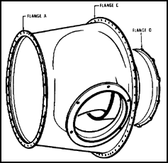
Figure 9.8. Exhaust Duct, -702.
9.9. REDUCTION GEARBOX
Located at the front of the engine is the reduction gearbox, which consists of two magnesium alloy castings bolted to the front flange of the exhaust duct. A cross-section view of the reduction gearbox is illustrated in figure 9.9.
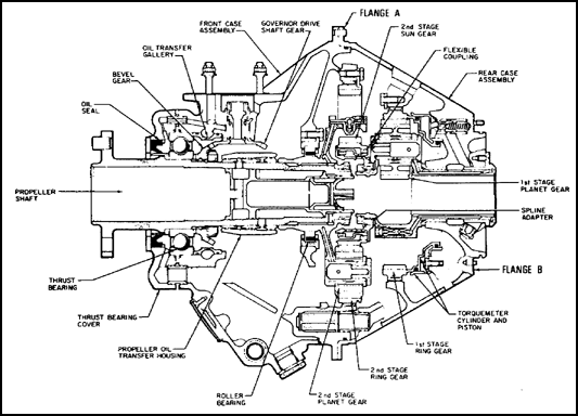
Figure 9.9. Reduction Gearbox.
The first stage of reduction is contained in the rear case. Torque from the power turbine is transmitted through the power turbine shaft to the first stage sun gear. The spur-gear end of the sun gear drives the three planetary gears in the first stage planet carrier. The first stage ring gear is located in helical splines in the rear case assembly. The torque developed by the power turbine is transmitted through the sun gear and planet gears to the ring gear. This results in rotation of the planetary carrier. The ring gear, though secured by the helical splines, is allowed to move axially between the case and three retaining plates. This movement is used in the torquemeter located inside the rear gearbox assembly, which is discussed in paragraph 9.16.
The second stage of reduction is contained in the reduction gearbox front case. The first stage planet carrier is attached to the second stage sun gear by a flexible coupling which also dampens any vibrations between the two rotating masses. The second stage sun gear drives five planet gears in the second stage carrier. A second stage ring gear is fixed by splines to the reduction gearbox front case and secured by three bolted retaining plates. The second stage carrier is in turn splined to the propeller shaft and secured by a retaining nut and shroud washer.
The accessories located on the reduction gearbox front case are driven by a bevel drive gear, mounted on the propeller shaft behind the thrust bearing assembly. Propeller thrust loads are absorbed by a flanged ball bearing located in the front face of the reduction gearbox centerbore. The thrust bearing cover is secured to the front of the reduction gearbox, and it has a removable oil seal retaining ring for replacement of the oil seal.
9.10. ACCESSORY GEARBOX
Located at the rear of the engine is the accessory gearbox. It consists of two magnesium alloy castings attached to the rear flange of the compressor inlet case by 16 studs. The front casting, provided with front and rear O-rings, forms an oil-tight diaphragm between the oil tank compartment of the inlet case and the accessory drives. The accessory drive gearbox is illustrated in figure 9.10.
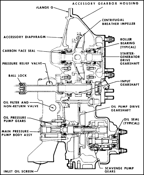
Figure 9.10. Accessory Gearbox Cross Section, -702.
The rear casting forms an accessory gearbox cover with support bosses for the accessory drive bearings and seals. The internal scavenge oil pump is secured inside the housing, and a second scavenge pump is externally mounted. Mounting pads and studs are located on the rear face for the combined starter-generator, the fuel control unit with the sandwich-mounted fuel pump, and the N1 tachometer-generator. Three additional pads are available for optional requirements; see figure 9.11.
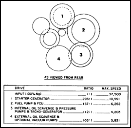
Figure 9.11. Accessory Gearbox Train.
An oil tank filler cap and dipstick are located at the eleven o'clock position on the rear housing. A centrifugal oil separator mounted on the starter-generator's drive gearshaft separates the oil from the engine breather air in the accessory gearbox housing.
9.11. BEARING INSTALLATION
The compressor rotor assembly is supported and secured in the rear section of the gas generator case by two bearings. The outer race of No. 1 ball bearing is held in its flexible housings by a special nut and keywasher. The split inner race, spacer, and rotor seal are stacked against a shoulder on the compressor rear hub shaft and secured by a cup-washer and special nut. The outer flange of the No. 2 roller bearing is attached to the gas generator centerbore by four bolts and tablock washers.
The compressor turbine disk holds the plain inner race stacked in position between front and rear rotor seals on the compressor front stubshaft and a shoulder on the stubshaft. The bearing installation of the T74 engine is illustrated in figure 9.12.
The power turbine disk and shaft assembly is supported and secured in the power turbine shaft housing by the No. 3 and No. 4 bearings. Bearing No. 3 is a roller type, and No. 4 is a ball type.
9.12. SUMMARY
The T74 is a light-weight, free-power turbine engine designed for use in fixed-wing aircraft. It has two independent turbines, one driving a compressor in the gas generator section, and the second driving a reduction gearing for a propeller installation.
The different engine sections bolt together at flanges, which are identified by letters. Numbers are used to identify locations or stations on the engine.
The compressor is a three-stage axial rotor, which is housed in the gas generator case. Located forward of the compressor is the combustion chamber. The combustion chamber is of the annular reverse-flow type. Fourteen fuel nozzles are mounted at the front end of the combustion chamber liner. The two single-stage turbine rotors are located in the center of the annular combustion chamber. The compressor turbine assembly is splined to the compressor front hub. The power turbine rotor drives the reduction gearing through the power turbine shaft.
Ahead of the combustor and turbine assemblies is the exhaust duct. The duct is attached to the front flange of the gas generator.
Located at the front of the engine are the reduction gearbox and propeller shaft. The accessory drive gearbox is attached to the aft flange of the compressor inlet case at the rear of the engine.
The engine has four main bearings. Numbers 1 and 4 are ball bearings, and 2 and 3 are roller bearings.
Section II. Major Engine Systems
9.13. GENERAL
The T74-CP-702 has four major engine systems: the bleed air system, lubrication system, fuel system, and instrumentation and ignition system. Each of these systems is essential for safe engine operation. The section discusses each system in detail in the paragraphs that follow.
9.14. BLEED AIR SYSTEMS
The engine has three separate bleed air systems: a compressor bleed air control, a bearing compartment airseal, and a turbine disk cooling system. The engine is also equipped for cabin-pressurization air. The following subparagraphs describe the bleed air systems.
![]() a. The compressor bleed air system. Automatically opening a valve in the gas generator case to spill interstage compressor air, the compressor bleed air system thereby prevents compressor stalls at low engine speeds. The valve closes gradually as higher engine speeds are attained.
a. The compressor bleed air system. Automatically opening a valve in the gas generator case to spill interstage compressor air, the compressor bleed air system thereby prevents compressor stalls at low engine speeds. The valve closes gradually as higher engine speeds are attained.
![]() b. Bearing compartment seals. Pressure air is used to seal the 1st, 2d, and 3d bearing compartments and also to cool both the compressor and the power turbines.
b. Bearing compartment seals. Pressure air is used to seal the 1st, 2d, and 3d bearing compartments and also to cool both the compressor and the power turbines.
![]() c. Turbine disk cooling system. The compressor and power turbine disks are both cooled by compressor discharge air bled from the straightening vane area of the diffuser. It is then metered through holes in the compressor turbine vane support into the turbine hub baffle, where it divides into three paths. Some of the air is metered to cool the rear face of the compressor turbine disk, and some to pressurize the bearing seals. The air is then led forward through passages in the compressor turbine hub to cool the front face of the compressor turbine. A portion of this cooling air is also led through a passage in the center of the interstage baffle to the rear face of the power turbine disk. The remaining air is used to cool the front face of the power turbine disk. The cooling air from both of the turbine disks is dissipated into the main gas stream flow to the atmosphere.
c. Turbine disk cooling system. The compressor and power turbine disks are both cooled by compressor discharge air bled from the straightening vane area of the diffuser. It is then metered through holes in the compressor turbine vane support into the turbine hub baffle, where it divides into three paths. Some of the air is metered to cool the rear face of the compressor turbine disk, and some to pressurize the bearing seals. The air is then led forward through passages in the compressor turbine hub to cool the front face of the compressor turbine. A portion of this cooling air is also led through a passage in the center of the interstage baffle to the rear face of the power turbine disk. The remaining air is used to cool the front face of the power turbine disk. The cooling air from both of the turbine disks is dissipated into the main gas stream flow to the atmosphere.
9.15. LUBRICATION SYSTEM
The T74 engine oil system is designed to provide a constant supply of clean lubricating oil to the engine bearings, reduction gears, torquemeter, propeller, and all accessory drive gears. The oil system consists of the components covered in the following subparagraphs. A schematic of the -702 engine lubrication system is illustrated in figure 9.13.
![]() a. The oil tank is part of the compressor inlet case. The tank has a total capacity of 2. 3 gallons of which 1.5 gallons are usable. This capacity allows for oil expansion of approximately 0.8 gallons.
a. The oil tank is part of the compressor inlet case. The tank has a total capacity of 2. 3 gallons of which 1.5 gallons are usable. This capacity allows for oil expansion of approximately 0.8 gallons.
The oil tank has an oil filler neck and a quantity dipstick and cap which protrudes through the accessory gearbox housing at the 11 o'clock position. An anti-flooding and breather arrangement, located in the highest point of the oil tank, prevents flooding of the accessory gearbox if the oil tank is overfilled. A drain plug is mounted in the bottom of the tank.
![]() b. A gear-type oil pressure pump is located in the lowest part of the tank. The pump consists of two gears contained in a cast housing, bolted to the front face of the accessory diaphragm. It is driven by the accessory gearshaft which drives the internal double-element scavenge pump. The oil pump has an inlet filter screen, check valve, and relief valve.
b. A gear-type oil pressure pump is located in the lowest part of the tank. The pump consists of two gears contained in a cast housing, bolted to the front face of the accessory diaphragm. It is driven by the accessory gearshaft which drives the internal double-element scavenge pump. The oil pump has an inlet filter screen, check valve, and relief valve.
![]() c. The oil filter assembly consists of a disposable cartridge type filter element with a perforated flanged end, bypass valve, and check valve. The filter assembly housing is located in the compressor inlet case at the 3 o'clock position. If the filter becomes clogged, the increased pressure opens the bypass valve, and an alternate passage for unfiltered oil to flow through the engine is used. The check valve, positioned in the end of the housing, prevents gravity flow into the engine after shutdown and permits the filter element to be changed without having to drain the oil tank.
c. The oil filter assembly consists of a disposable cartridge type filter element with a perforated flanged end, bypass valve, and check valve. The filter assembly housing is located in the compressor inlet case at the 3 o'clock position. If the filter becomes clogged, the increased pressure opens the bypass valve, and an alternate passage for unfiltered oil to flow through the engine is used. The check valve, positioned in the end of the housing, prevents gravity flow into the engine after shutdown and permits the filter element to be changed without having to drain the oil tank.
![]() d. The centrifugal breather consists of a shrouded aluminum alloy impeller secured to the rear face of the starter-generator gearshaft by a retaining ring. Breather air flows radially inward through the rotating impeller housing where the oil particles are separated from the air mist by centrifugal force. The oil particles are thrown outward and drain freely to the bottom of the accessory gearbox. The air is then routed through a transfer tube to a breather boss on the rear face of the accessory housing where a connection for an overboard vent line is installed.
d. The centrifugal breather consists of a shrouded aluminum alloy impeller secured to the rear face of the starter-generator gearshaft by a retaining ring. Breather air flows radially inward through the rotating impeller housing where the oil particles are separated from the air mist by centrifugal force. The oil particles are thrown outward and drain freely to the bottom of the accessory gearbox. The air is then routed through a transfer tube to a breather boss on the rear face of the accessory housing where a connection for an overboard vent line is installed.
![]() e. The oil-to-fuel heater assembly is essentially a heat exchanger which uses heat from the engine oil lubricating system to preheat the fuel in the engine fuel system. The heater has a Vermatherm element, which senses fuel temperature, and consists of a highly expansive material sealed in a metallic chamber. The expansion force is transmitted through a diaphragm and plug to a piston. The element senses outlet fuel temperatures and, at temperatures above 70° F, starts to close the core valve and simultaneously opens the bypass valve. At 90° F, the core valve is completely closed and the oil bypasses the heater core.
e. The oil-to-fuel heater assembly is essentially a heat exchanger which uses heat from the engine oil lubricating system to preheat the fuel in the engine fuel system. The heater has a Vermatherm element, which senses fuel temperature, and consists of a highly expansive material sealed in a metallic chamber. The expansion force is transmitted through a diaphragm and plug to a piston. The element senses outlet fuel temperatures and, at temperatures above 70° F, starts to close the core valve and simultaneously opens the bypass valve. At 90° F, the core valve is completely closed and the oil bypasses the heater core.
9.16. PRESSURE AND SCAVENGE OIL SYSTEMS
Oil for lubrication of engine parts is supplied under pressure by the pressure oil system. This oil is then returned to the oil tank by the scavenge oil system. The following subparagraphs discuss the pressure and scavenge oil systems.
![]() a. The pressure oil system supplies oil at 85 to 95 psi to the reduction gearbox where it is divided into two branches. One branch is led to the first stage reduction gears, splines, torquemeter, and number 3 and 4 bearings. Pressure oil to the torquemeter is led through a metering valve which controls the flow into the torquemeter chamber. The bearings and gears are lubricated by oil spray jets. The second branch supplies oil to the propeller governor unit, the accessory drive gears, and propeller thrust bearing.
a. The pressure oil system supplies oil at 85 to 95 psi to the reduction gearbox where it is divided into two branches. One branch is led to the first stage reduction gears, splines, torquemeter, and number 3 and 4 bearings. Pressure oil to the torquemeter is led through a metering valve which controls the flow into the torquemeter chamber. The bearings and gears are lubricated by oil spray jets. The second branch supplies oil to the propeller governor unit, the accessory drive gears, and propeller thrust bearing.
![]() b. The scavenge oil system includes two double-element scavenge pumps connected by internal passages and lines to two main external transfer tubes. One pump is secured inside the accessory gearbox and the other is externally mounted. They are contained in separate housings and driven off accessory gearshafts.
b. The scavenge oil system includes two double-element scavenge pumps connected by internal passages and lines to two main external transfer tubes. One pump is secured inside the accessory gearbox and the other is externally mounted. They are contained in separate housings and driven off accessory gearshafts.
The oil from the No. 1 bearing compartment is returned by gravity through an internal cored passage to the bottom of the compressor inlet case and then through internal passages in the oil tank and accessory diaphragm into the accessory gearbox. Number 2 bearing oil drains down from its compartment into an external sump leading rearward to the bottom of the tank. It is then scavenged to the scavenge pump which forces the oil into the accessory gearbox. The oil from the centrifugal breather and the input gearshaft and bearings drains to the bottom of the accessory gearbox. It is then scavenged from the gearbox together with the oil from No. 1 and 2 bearings by the rear element of the double-element internal scavenge pump. The internal scavenge pump is driven by a quillshaft from the main oil pump in the oil tank. The external scavenge pump scavenges any reduction gearbox oil which drains rearward when the engine is in extreme climbing attitudes. Oil from the propeller governor, front thrust bearing, reduction gear, and torquemeter bleed orifice drains into the reduction gearbox sump. The oil is then scavenged by the external scavenge pump through the external transfer tube to the accessory gearbox housing. The oil from both internal and external scavenge pumps is forced through a T fitting into the airframe oil cooler, where the oil is cooled and passed on to the oil tank. The normal oil operating temperature is 74° to 80° C.
9.17. TORQUEMETER
The torquemeter is a hydromechanical torque-measuring device located inside the first stage reduction gear housing. The torquemeter gives an accurate indication of the torque being produced by the power turbine. The torque pressure value is obtained by tapping the two outlets on the top of the reduction gearbox case. The pressure differential between the two outlets is then read on an instrument which indicates the correct torque pressure.
9.18. FUEL SYSTEM
The T74 basic fuel system consists of a single, engine-driven, fuel pump; p fuel control unit, temperature compensator, and starting control; and a dual fuel manifold with 14 simplex fuel nozzles. Two drain valves are mounted on the gas generator case to insure drainage of residual fuel after engine shutdown after a false or aborted start. The -702 fuel system is illustrated in figure 9.14.
![]() a. The fuel pump is a positive displacement gear-type pump and is driven off the accessory gearbox. Fuel from a booster pump enters the fuel pump through a screen filter and then on to the pump gear chamber, from where the fuel is pumped at high pressure to the fuel control unit. The filter screen is spring loaded and should it become blocked, an increase in fuel pressure differential overcomes the spring, lifts the screen from its seat, and allows unfiltered fuel to flow into the system. The fuel control unit returns bypassed fuel from the fuel control unit to the pump inlet; see the internal line in figure 9.14.
a. The fuel pump is a positive displacement gear-type pump and is driven off the accessory gearbox. Fuel from a booster pump enters the fuel pump through a screen filter and then on to the pump gear chamber, from where the fuel is pumped at high pressure to the fuel control unit. The filter screen is spring loaded and should it become blocked, an increase in fuel pressure differential overcomes the spring, lifts the screen from its seat, and allows unfiltered fuel to flow into the system. The fuel control unit returns bypassed fuel from the fuel control unit to the pump inlet; see the internal line in figure 9.14.
![]() b. The fuel control unit is mounted on the engine-driven fuel pump and is driven at a speed proportional to compressor turbine speed (N1). The control determines the proper fuel schedule for the engine to produce the power required as established by controlling the speed of the compressor turbine (N1). Engine power output is directly dependent upon compressor turbine speed. The fuel control governs the N thereby governing the power output of the engine. Control of N1 is accomplished by regulating the amount of fuel supplied to the combustion chamber.
b. The fuel control unit is mounted on the engine-driven fuel pump and is driven at a speed proportional to compressor turbine speed (N1). The control determines the proper fuel schedule for the engine to produce the power required as established by controlling the speed of the compressor turbine (N1). Engine power output is directly dependent upon compressor turbine speed. The fuel control governs the N thereby governing the power output of the engine. Control of N1 is accomplished by regulating the amount of fuel supplied to the combustion chamber.
![]() c. The temperature compensator is mounted on the compressor case with the bimetallic disks extending into the inlet air stream. The temperature compensator is illustrated in figure 9.15.
c. The temperature compensator is mounted on the compressor case with the bimetallic disks extending into the inlet air stream. The temperature compensator is illustrated in figure 9.15.
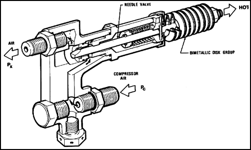
Figure 9.15. Temperature Compensator,-700.
Compressor discharge pressure (PC) is applied to the compensator. This pressure source is used to produce a pressure signal to the fuel control unit. The compensator changes the pressure signal to the fuel control to produce an acceleration schedule, based on inlet air temperature, to prevent compressor stall or excessive turbine temperature.
![]() d. The starting control consists of a ported plunger sliding in a ported housing. A schematic of the starting control fuel flow is shown in figure 9.16.
d. The starting control consists of a ported plunger sliding in a ported housing. A schematic of the starting control fuel flow is shown in figure 9.16.
Rotational movement of the input lever is converted to a linear movement of the plunger through a rack and pinion engagement. A pressurizing valve, located at the inlet to the control, maintains a minimum pressure in the fuel control to insure correct metering. This valve permits the primary manifold to fill initially for lightup, and as pressure increases in the control, the transfer valve opens. This allows fuel to flow into secondary manifold.
![]() e. The fuel manifold assembly delivers a constant supply of high pressure fuel from the starting control to two sets of seven fuel manifold adapters with simplex nozzles. The dual manifold consists of 28 short fuel transfer tubes fitted with O-rings at each end and interconnected by 14 fuel manifold adapters. Locking plates keep the transfer tubes in proper alignment, secured by two bolts to a mounting boss on the circumference of the gas generator case. Individual transfer tubes or fuel nozzles can be removed and replaced without necessarily disconnecting the remainder of the set. The fuel manifold assembly is illustrated in figure 9.17.
e. The fuel manifold assembly delivers a constant supply of high pressure fuel from the starting control to two sets of seven fuel manifold adapters with simplex nozzles. The dual manifold consists of 28 short fuel transfer tubes fitted with O-rings at each end and interconnected by 14 fuel manifold adapters. Locking plates keep the transfer tubes in proper alignment, secured by two bolts to a mounting boss on the circumference of the gas generator case. Individual transfer tubes or fuel nozzles can be removed and replaced without necessarily disconnecting the remainder of the set. The fuel manifold assembly is illustrated in figure 9.17.
The glow-plug type ignition system is used on the T74 engine for quick light-offs (starts), even at extremely low ambient temperatures. The basic system consists of a current regulator and two sets of tubes, two shielded plug leads, and two glow plugs. The following subparagraphs discuss the components in the ignition system.
![]() a. The current-regulator unit is normally secured to the accessory gearbox housing but can be remotely mounted if required. The regulator contains four electron tubes, shown in figure 9.18. Each tube has a pure iron filament surrounded by helium and hydrogen gas and enclosed in a glass envelope sealed to an octal base. The iron filament, having a negative co-efficient of resistance (resistance decreases with temperature increase caused by current flow), stabilizes the current flow across the tubes to a nearly constant value over a wide range of voltages. Each glow plug is wired in series with two parallel connected ballast tubes. Either glow plug may be selected for starting the engine. The tubes provide an initial current surge when switched on, which stabilizes to a constant value in approximately 30 seconds. The system heats the glow plugs for fast light-offs.
a. The current-regulator unit is normally secured to the accessory gearbox housing but can be remotely mounted if required. The regulator contains four electron tubes, shown in figure 9.18. Each tube has a pure iron filament surrounded by helium and hydrogen gas and enclosed in a glass envelope sealed to an octal base. The iron filament, having a negative co-efficient of resistance (resistance decreases with temperature increase caused by current flow), stabilizes the current flow across the tubes to a nearly constant value over a wide range of voltages. Each glow plug is wired in series with two parallel connected ballast tubes. Either glow plug may be selected for starting the engine. The tubes provide an initial current surge when switched on, which stabilizes to a constant value in approximately 30 seconds. The system heats the glow plugs for fast light-offs.
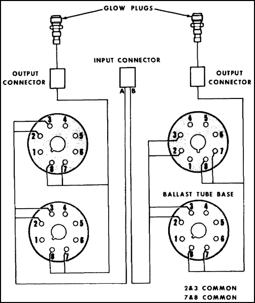
Figure 9.18. Current Regulator Circuit.
![]() b. The glow plug consists of a heating element fitted into a short conventional type plug body. A cross-section illustration of a glow plug is shown in figure 9.19.
b. The glow plug consists of a heating element fitted into a short conventional type plug body. A cross-section illustration of a glow plug is shown in figure 9.19.
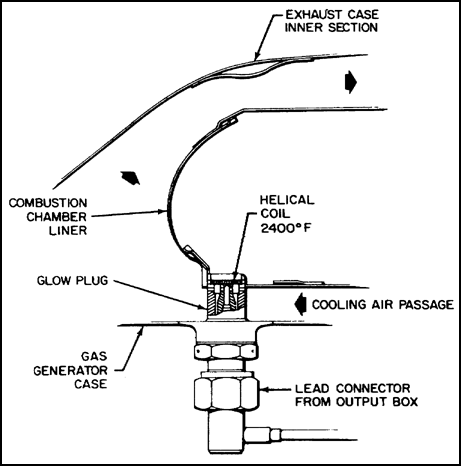
Figure 9.19. Glow Plug.
The plugs are secured to the gas generator case in threaded bosses. The heating element consists of a helically wound coil which lies slightly below the end of the plug body. During starting procedures, the fuel sprayed by the fuel nozzles runs down along the lower wall of the combustion chamber liner and into the helical coil in the glow plug body. The fuel is vaporized and ignited by the hot coil element which heats up to approximately 2,400° F. Three air holes in the plug body allow compressor discharge air from the gas generator case into the plug body, then past the hot coil in the combustion chamber liner to produce a hot streak or torching effect which ignites the remainder of the fuel. The air also serves to cool the coil elements when the engine is running with the glow plugs switched off.
9.20. INSTRUMENTATION
The following instrumentation is considered necessary for normal operation.
![]() a. The interturbine temperature sensing system is designed to provide the pilot with an accurate indication of engine operating temperature taken between the gas generator and power turbines. The system shown in figure 9.20 consists of twin leads, two busbars, and 10 individual chromel-alumel thermocouple probes connected in parallel. Each probe protrudes through a threaded boss on the power turbine stator housing into an area adjacent to the leading edge of the power turbine vanes. This system generates its own electric current.
a. The interturbine temperature sensing system is designed to provide the pilot with an accurate indication of engine operating temperature taken between the gas generator and power turbines. The system shown in figure 9.20 consists of twin leads, two busbars, and 10 individual chromel-alumel thermocouple probes connected in parallel. Each probe protrudes through a threaded boss on the power turbine stator housing into an area adjacent to the leading edge of the power turbine vanes. This system generates its own electric current.
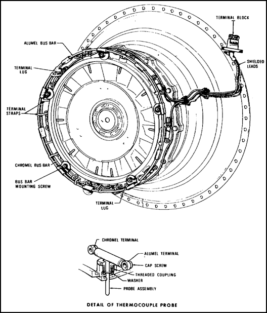
Figure 9.20. Interturbine Temperature Thermocouple Assembly, -700.
![]() b. The oil temperature indicator measures the temperature of the oil as it leaves the delivery side of the oil pressure pump. The oil temperature bulb is mounted on the accessory gearbox housing. This system uses 28v dc from the aircraft electrical system.
b. The oil temperature indicator measures the temperature of the oil as it leaves the delivery side of the oil pressure pump. The oil temperature bulb is mounted on the accessory gearbox housing. This system uses 28v dc from the aircraft electrical system.
![]() c. The oil pressure indicator measures oil pressure in psi at the delivery side of the oil pump. The oil pressure transmitter is mounted just above the oil temperature bulb on the accessory gearbox housing.
c. The oil pressure indicator measures oil pressure in psi at the delivery side of the oil pump. The oil pressure transmitter is mounted just above the oil temperature bulb on the accessory gearbox housing.
![]() d. The turbine tachometer registers compressor turbine speed (N1) as a percentage of maximum rpm. Propeller shaft speed is registered in hundreds of rpm. The tachometer-generator for the N1 is mounted at the 5 o'clock position on the accessory gearbox and is driven from the internal scavenge pump. The propeller tachometer-generator (N2) is mounted on the right side of the reduction gearbox front case and is driven by a bevel gear on the propeller shaft. The N1 and N2 tachometer-generators produce their own electrical current.
d. The turbine tachometer registers compressor turbine speed (N1) as a percentage of maximum rpm. Propeller shaft speed is registered in hundreds of rpm. The tachometer-generator for the N1 is mounted at the 5 o'clock position on the accessory gearbox and is driven from the internal scavenge pump. The propeller tachometer-generator (N2) is mounted on the right side of the reduction gearbox front case and is driven by a bevel gear on the propeller shaft. The N1 and N2 tachometer-generators produce their own electrical current.
![]() e. The torquemeter indicating system registers engine output power in psi of torque. The transmitter converts oil pressure to an electrical signal that registers engine torque on a gage in the pilot's cockpit.
e. The torquemeter indicating system registers engine output power in psi of torque. The transmitter converts oil pressure to an electrical signal that registers engine torque on a gage in the pilot's cockpit.
9.21. SUMMARY
The Pratt and Whitney T74-CP-702 has four major engine systems. The compressor bleed-air system prevents the compressor from stalling during low engine speeds. Compressor bleed-air is also used for bearing compartment seals and turbine cooling.
The lubrication pressure system produces a constant supply of clean oil to the engine bearings, reduction gears, torquemeter, propeller, and accessory gears. The oil is then transferred back to the oil tank by the internal and external scavenge pumps.
The basic fuel system consists of a single engine-driven pump, fuel control unit, temperature compensator starting control, fuel manifold, and 14 simplex fuel nozzles. The fuel control determines the fuel flow to the engine to produce the power required. The temperature compensator sends an air pressure signal to the fuel control to prevent compressor stall or excessive turbine temperature. The starting control permits the primary manifold to fill for engine starts. The fuel manifold delivers fuel to two sets of seven simplex nozzles.
The glow plug ignition system is capable of quick light-offs at extremely low ambient temperature. The fuel is vaporized and ignited by the hot coil element in the glow plug. The engine is equipped with instrumentation to monitor engine operation during flight measures temperature in the turbine section.
Turbine tachometers register N1 speed as a percentage of maximum gas generator rpm. The propeller tachometers (N2)register shaft speed in hundreds of rpm. Each indicator is directly responsive to a tachometer-generator unit attached to a corresponding engine section.
Oil pressure is taken from the delivery side of the main oil pressure pump and registered in psi.
Oil temperature is taken from the delivery side of the oil pressure pump and registered in degrees centigrade.
The torquemeters indicate torque in psi applied to the propeller shaft.
Chapter 10
GENERAL ELECTRIC T700-GE-700
10.1. INTRODUCTION
General Electric is developing the T700-GE-700 turboshaft engine for the U. S. Army Utility Tactical Transport Aircraft System (UTTAS). The T700 is designed to operate in combat with improved reliability, easy maintenance, low fuel consumption, and extended operating life.
The T700 will operate with no visible smoke and at low noise levels. External lines and leads have been reduced in number and grouped for armoring protection. The engine also contains its own lubrication and electrical systems to reduce dependence on the airframe systems.
10.2. GENERAL DESCRIPTION
The T700 is an axial-flow, free-power, turboshaft engine rated at 1,500 shp. It has a five-stage axial, single-stage centrifugal compressor; an annular combustor; a two-stage gas generator (N1) turbine; and a two-stage power turbine. An engine-driven inlet particle separator is located ahead of the compressor. For field maintenances, the engine breaks down into four modules: controls and accessories, cold section, hot section, and power turbine.
The engine is constructed of corrosion-resistant steel except for a titanium axial-compressor casing, aluminum inlet-separator frame, and magnesium gearbox case. The engine dimensions in inches are length 47, height 23, and width 25. A cutaway illustration of the T700-GE-700 is shown in figure 10.1.
10.3. CENTRIFUGAL INLET SEPARATOR
Figure 10.2 shows the centrifugal inlet separator and a schematic of its operation. The inlet air passes through the fixed separator swirl vanes which swirl the air, and centrifugal force throws the particles to the separator collection scroll. The scroll is scavenged by an engine-driven blower mounted on the accessory gearbox.
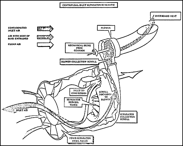
Figure 10.2. Centrifugal Inlet Separator.
10.4. COMPRESSOR
The compressor has five axial stages and one centrifugal stage. The inlet guide vanes and the first and second stage stator vanes in the compressor vary their angle of attack according to compressor speed. The centrifugal impeller is mounted aft and on the same shaft as the axial compressor. One of the major design differences of the T700 is that the axial-compressor rotor stage blades and disks are one-piece castings. This means better rotor integrity and also easier buildup and overhaul. The compressor has very few blades, 332 total. This is about one-third the number in comparable current engines. Stages one and five have borescope ports for inspections. Just aft of the centrifugal impeller is the diffuser passage.
10.5. COMBUSTOR
The annular combustion chamber is located aft of the diffuser. Engine durability and time between overhauls (TBO) are directly related to the heat of the combustor. If the combustor can develop the power required at a lower temperature, component service life can be increased.
The combustor has twelve vaporizing fuel injectors and two atomizing start-fuel nozzles. The axial type vaporizing combustor operates with a lower peak temperature factor. Axial flow ensures minimum liner area and hence minimizes the amount of secondary cooling air to be mixed into the hot gas stream. The annular combustion chamber can be seen in figure 10.1.
10.6. GAS GENERATOR TURBINE
The T700 gas generator turbine is a two-stage, air-cooled, high-performance, axial-flow turbine. The modular concept has been used in the gas generator turbine design for ease of assembly and maintenance. The turbine is divided into easily accessible submodules consisting of the first stage turbine nozzle and the turbine rotor.
The first stage nozzle submodule consists of 24 air-cooled cast vane segments brazed in pairs. These twelve pairs are assembled to the inner support and held in place by a retaining ring with bolts.
The rotor submodule consists of the turbine rotor combined with the second nozzles, supports, and shrouds. Both first and second stage disks, cooling plates, and turbine blades are clamped by five short tiebolts. Five longer tiebolts clamp this rotor assembly to the forward shaft through the forward coupling. Loosening these five longer tiebolts does not disturb the rotor assembly itself, permitting simple maintenance without special tools. Thirteen second-stage nozzle segments of two vanes each are held by the outer support, which is also assembled with the first stage shroud segments and second stage shroud support.
All airfoils (vanes) are internally cooled. The first stage nozzle leading edge is air-cooled, with the air exiting through holes in the vane airfoils. The midchord region is convection-cooled, with cooling air exiting both through pressure holes and trailing edge slots. Cooling air for the second stage nozzle is bled from the centrifugal compressor exit and piped back through the turbine casting. The air enters the second stage nozzle through bushings and cools the nozzles by internal airflow exiting through trailing edge and inner band holes. The turbine blades are air-cooled through radial holes. Air enters through the dovetail and exits at the tip. The first stage blades also employ trailing edge holes for cooling.
10.7. POWER TURBINE
This component is a two-stage uncooled tip-shrouded design with replaceable turbine blades and nozzle segments. The output shaft governing speed range is from 17,000 to 23,000 rpm with a maximum rated speed of 24,000 rpm.
The power turbine is a self-contained module which can be disassembled and reassembled to the gas generator without special tools.
The rotor assembly consists of the third and fourth stage disks mounted on a drive shaft supported by four bearings. The third stage disk is secured to the drive shaft by a flange, allowing quick removal from the drive shaft without removal of the aft sump or rear frame. The third stage disk has 46 tip-shrouded blades attached to the disk through conventional dovetails and retained axially by bent locking strips. A similar arrangement is used on stage four where 50 blades are employed.
The drive shaft is a hollow one-piece unit splined to the short output shaft at the forward end. An integral feature of the drive shaft is the torque sensor that mechanically displays the total twist of the drive shaft, which is electrically sensed and processed. This mechanical display of total twist is accomplished by a reference shaft that is pinned to the front end and extends back to the aft end, where it is free to rotate relative to the drive shaft. The relative rotation is due to transmitted torque, and the phase angle between the reference surfaces is electronically sensed by two pickups, one sensing five teeth on the reference shaft, the other sensing five teeth on the drive shaft.
Both stages of each turbine nozzle are cast in segments. The third stage has six segments of six vanes each, and the fourth stage has 10 segments of five vanes each. The static tip shrouds are replaceable in four segments each and are of open cell honeycomb arrangement.
10.8. BEARING ARRANGEMENT
Figure 10.1 shows the T700-GE-700 bearing and frame arrangement. The four bearings and shaft arrangement at the front of the axial compressor isolate the driveshaft from the engine.
Circumferential carbon seals are used on the power turbine shaft, and labyrinth seals are used on the gas generator shaft. The front frame has eighteen deswirl vanes which are part of the structure.
10.9. LUBRICATION SYSTEM
A schematic of the lubricating system is shown in figure 10.3. The oil tank is built into the inlet particle separator. All scavenge lines have magnetic chip detection for fault isolation. An emergency lubrication system has been built into the design for assuring continued bearing operation after loss of oil from any cause. Small oil reservoirs are included in each bearing sump, and are kept full during normal operation by the oil pressure pumps. Oil is always bleeding out of these reservoirs at a slow rate. Air jets, also continuous, act as "foggers" for this oil bleed and provide oil mist lubrication at all times. This continues for at least six minutes even if the oil supply fails. A fuel-oil heat exchange is a self-contained oil cooler and fuel de-icer.
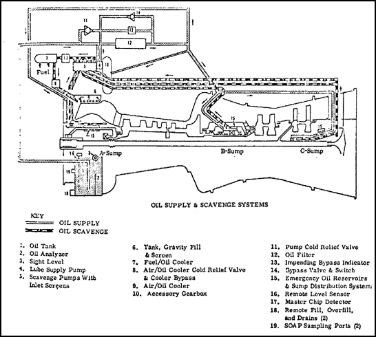
Figure 10.3. Lubrication System Schematic.
10.10. MAINTAINABILITY
The engine has been designed for ease of servicing and maintenance. Borescope inspections can be made in critical areas where sand and dust erosion and clogging, corrosion, and foreign object damage can occur and in other critical areas where inspections are necessary.
The T700 design offers the following maintenance benefits: no special tools required for module replacement, no critical measurements required for module replacement, no component replacement at direct support. Any maintenance action requiring special tools is accomplished at depot level.
10.11. SCHEDULED MAINTENANCE
The T700-GE-700 engine has been designed to meet the required design life of 5,000 hours. The T700 is a durably designed engine and does not require frequent scheduled checks or adjustments. An example of this feature is that the fuel control requires no field adjustments.
10.12. SUMMARY
The General Electric T700-GE-700 turboshaft engine is presently being developed to power the Utility Tactical Transport Aircraft System (UTTAS). The engine is an axial-flow free-power turbine design, rated at 1, 536 shp. The engine is made up of four modules: accessory gearbox, cold section, hot section, and power turbine.
Mounted on the front of the engine is a centrifugal inlet particle separator to keep foreign objects from entering the compressor. The compressor has five axial stages and one centrifugal stage. The annular combustion chamber has 12 vaporizing fuel injectors and two atomizing start-fuel nozzles. The gas generator turbine and power turbine are two-stage axial flow turbines. An emergency oil system has been designed to ensure limited engine operation after loss of oil. The oil tank is built into the inlet separator.
The engine has been designed for improved reliability, easy maintenance, low fuel consumption, and extended operating life. All field maintenance can be performed without special tools. The engine can be internally inspected by the borescope method, rather than by engine teardown. The engine will have a design life of 5,000 hours.
GO TO: