

Krug - THICK EIGHT
| Range | 5,000 nm |
| Bearing | 360 degrees |
| Accuracy | 1.0 degree |
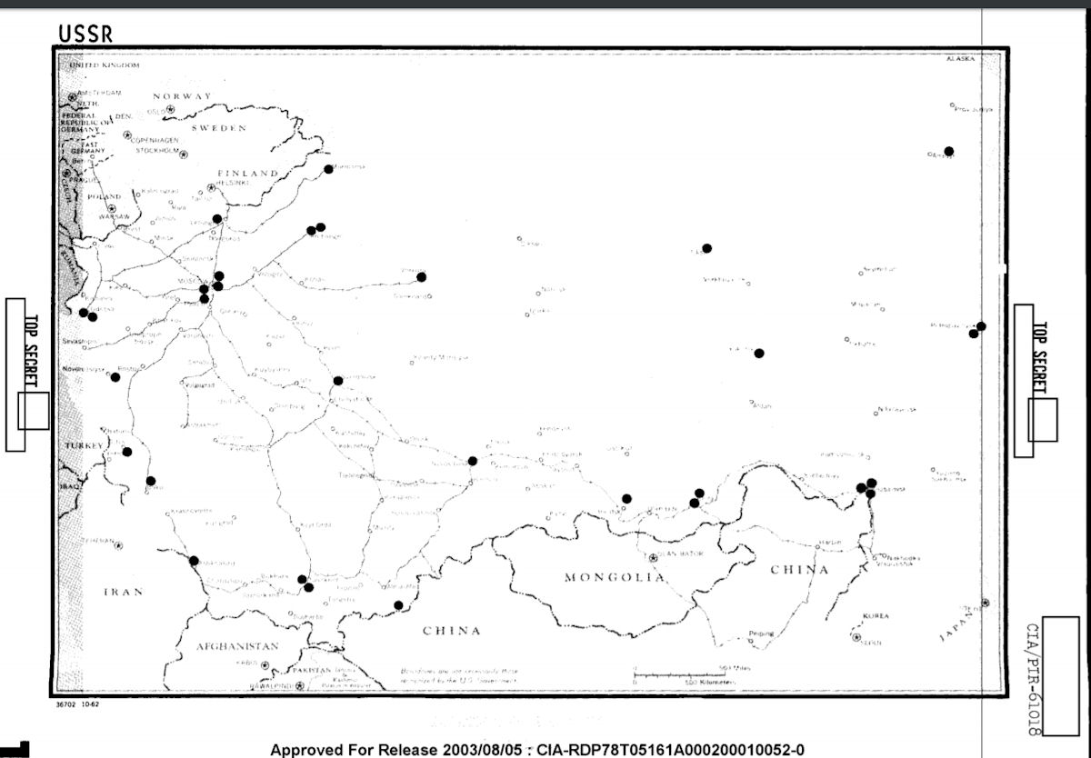
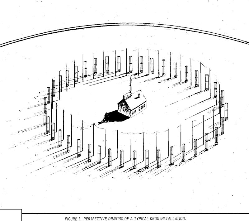
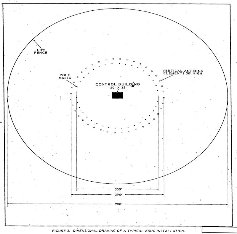
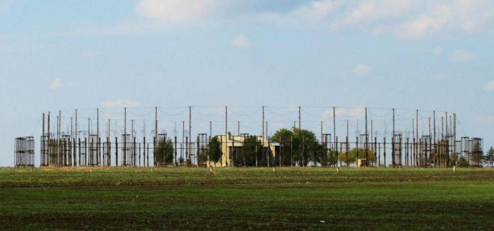
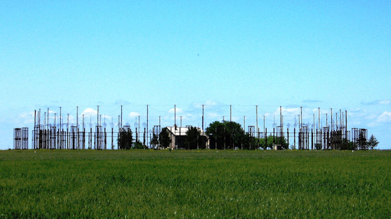
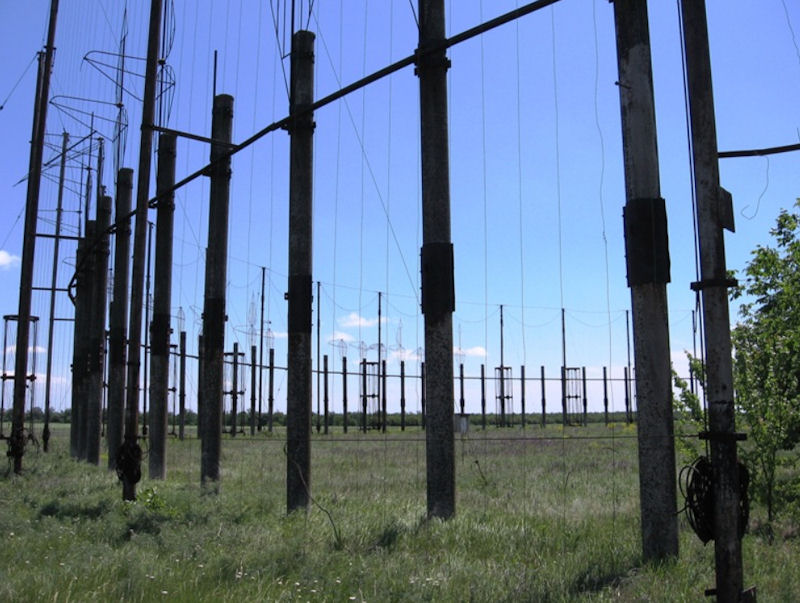
There were several different kinds of Soviet CDAA. The first kind were known to NATO as Krug arrays. Krug is Russian for circle, and it may be that Russia applied the term Krug to all CDAAs, but the Western use of the term refers only to the very large arrays 200-300 meters in diameter with a vertical screen (looking like a huge circular fence) about 105 meters in diameter surrounded by 40 large antenna towers. There were only 31 Krugs ever constructed.
The Soviets also constructed a smaller, generic, 8-antenna CDAA, (using the same caged antenna as the KRUG) which western intelligence referred to as a THICK EIGHT. This system was deployed in the Soviet Union, Warsaw Pact countries, and the technology sold to China. A third kind of CDAA was known to NATO as a Fix-24. This kind of array is 150-200 meters in diameter and contains concentric rings of antennas 45 and 130 meters in diameter. These antennas are very difficult to see even at the best Google Earth resolutions, but in some instances they are visible. There were 17 as many as probable Fix-24s.
Desmond Ball, Australian National University, 1989) reported that the GRU's network of DF and intercept stations "consists of the control station at Klimovsk and 11 other stations in various other parts of the USSR." It was created in the early 1950s to track any information concerning aircraft carriers of nuclear weapons of the SAC, NATO and NATO NATO, reconnaissance aircraft (AWACS, B-52, B-1 and B-2, S-135, SR- 71 and U-2, KS-135). In addition to communications between the crews of strategic bomber wings and flights of US reconnaissance aircraft and NATO countries, a radio survey of the satellite communications systems of the US Joint Chiefs of Staff was conducted. The direction and direction of the clients' movement on thousands of kilometers of removal was determined quite accurately by the direction of several ORPUs.
| |||
| ARKHANGELSK | 64°30'N | 40°45'E | |
| ARKHANGELSK SITE 1 | 64°25'N | 40°40'E | |
| ASHKABAD | 38°l0'N | 58°05'E | |
| BERINGOVSKIY | 63°04'N | 179°06'E | |
| CHITA SITE 1 | 52°05'N | 113°27'E | |
| CHITA SITE 2 | 52°l0'N | 113°30'E | |
| ILI | 43°58'N | 77°31'E | |
| KHABAROVSK SITE 1 | 48°30'N | 135°18'E | |
| KHABAROVSK SITE 2 | 48°25'N | 135°21'E | |
| KHABAROVSK SITE 3 | 48°23'N | 135°16'E | |
| KRASNODAR | 45°09'N | 38°47'E | |
| MOSCOW/PEROVO | 55°43'N | 37°59'E | |
| MOSCOW AREA SITE | 55°56'N | 37°37'E | |
| MURMANSK | 68°47'N | 32°55'E | |
| NOVOSIBIRSK | 55°15'N | 83°19'E | |
| ODESSA SITE 1 | 46°26'N | 30°30'E | |
| ODESSA SITE 2 | 46°31'N | 30°33'E | |
| OYEK AREA | 52°35'N | 104°32'E | |
| PETROPAVLOVSK SITE 1 | 53°02'N | 158°49'E | |
| PETROPAVLOVSK SITE 2 | 53°05'N | 158°22'E | |
| PODOLSK (VLASYEVO) | 55°28'N | 37°22'E | |
| PODOLSK (KLIMOVSK) | 55°23'N | 37°28'E | |
| RUSTAVI | 41°24'N | 45°07'E | |
| SUMGART | 40°45'N | 49°28'E | |
| SVERDLOVSK | 56°47'N | 60°55'E | |
| TASHKENT SITE 1 | 41°19'N | 69°26'E | |
| TASHKENT SITE 2 | 41°09'N | 69°25'E | |
| TISKI | 71°38'N | 128°41'E | |
| VEROLANTSY | 59°34'N | 29°49'E | |
| VORKUTA | 67°39'N | 63°50'E | |
| YAKUTSK | 61°55'N | 129°37'E | |
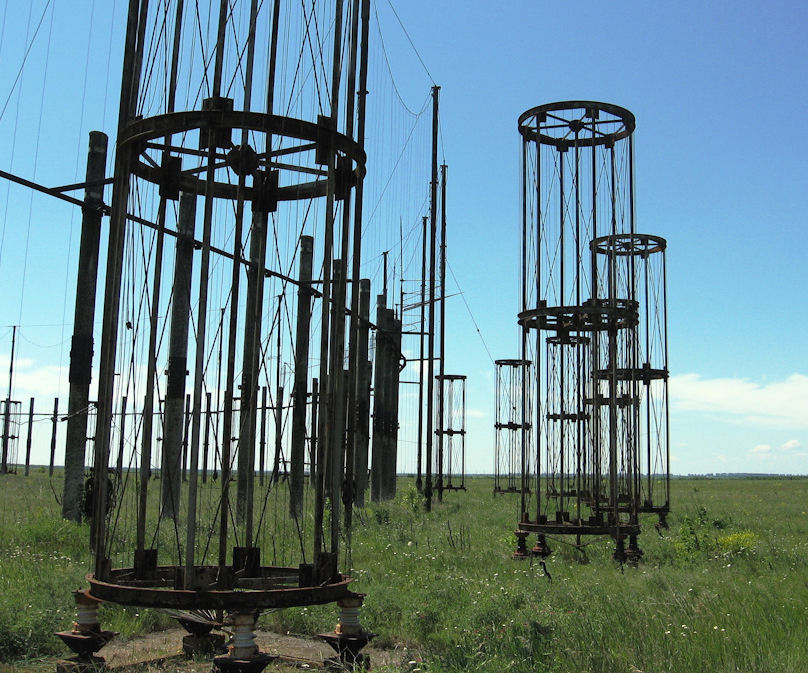
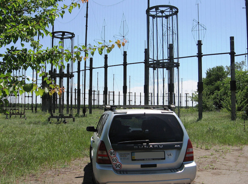
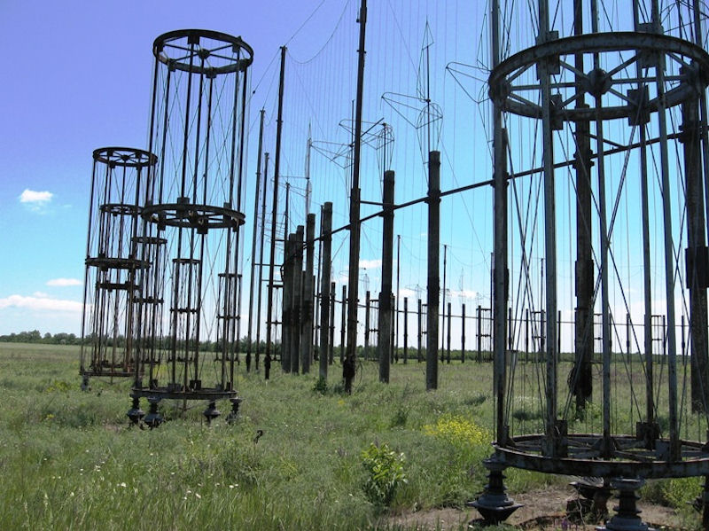
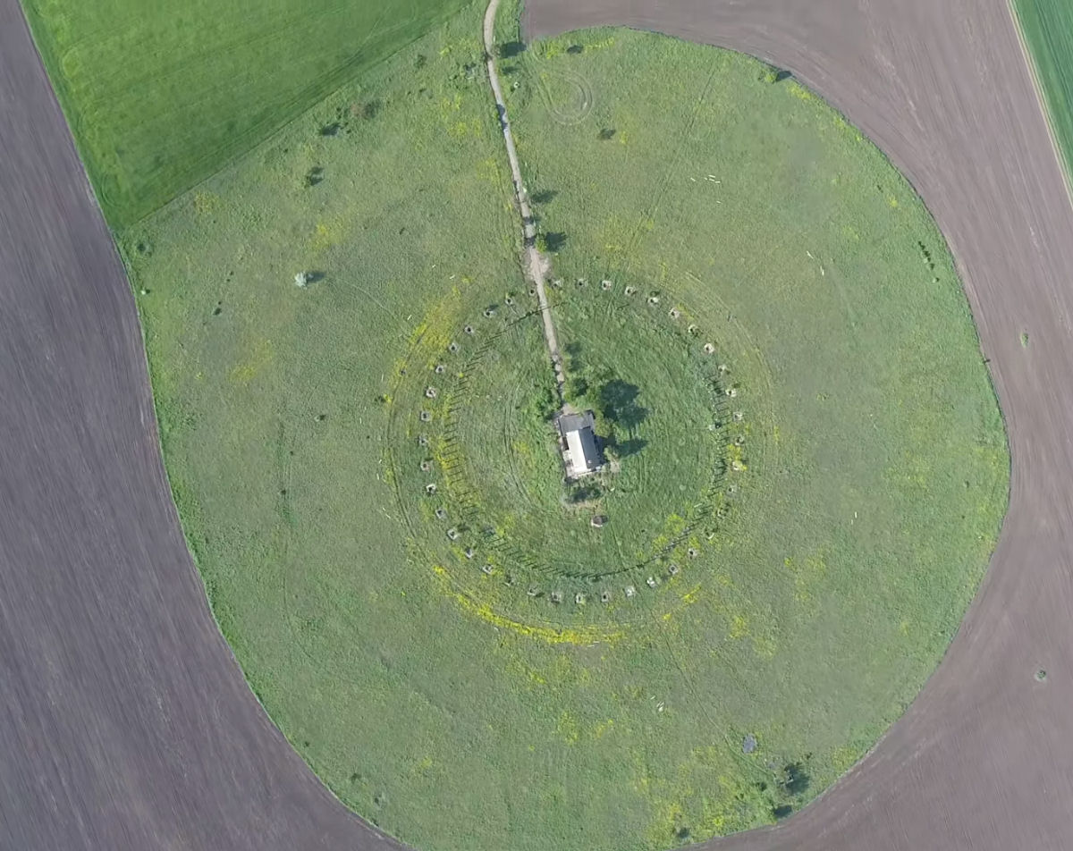
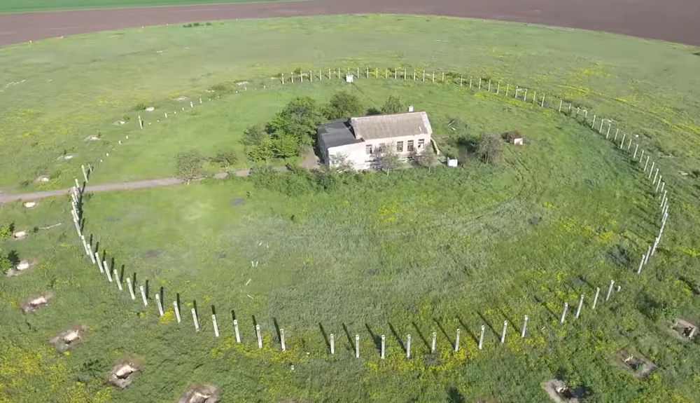
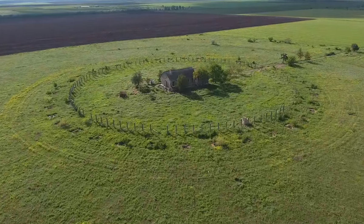
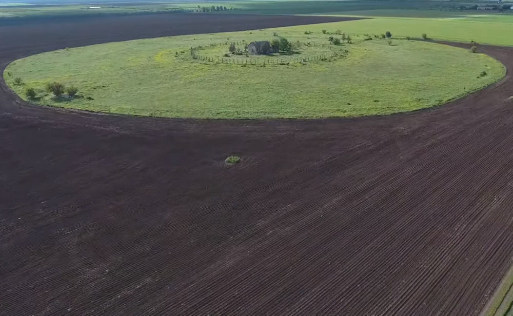
Elements of the antenna represent a platform in the form of a circle, with a diameter of 300 meters. On the perimeter were installed elements (vibrators), coated with chrome or other, corrosion-resistant metal. In the middle of the "Circle" stands a squat, one-story building - technical rooms for receiving and transmitting equipment. System "Circle", previously consisted of 2 concentric circles of 120 antennas with a height of 10 m in each - the receiving position of the route determination system (COT).
The essence of the direction finder's work consisted in determining the direction (direction) from which the radio signal came from. Uniformly located on the 120 meter ring, the antennas did not receive the signal front at the same time, but the cunning device in the house located in the center of the antenna field compared these signals and determined the priority direction. Of course, one direction is not enough to determine the position of the object, a distance, or several directions, was also needed - vectors from different points to one, the intersection. This method is called triangulation.
By the beginning of the 1960s, radio communications worldwide were overwhelmingly high-frequency manual Morse (HFMM) and high-frequency radioprinter (HFRP), and Soviet collection capabilities were geared toward this. There was a large establishmentof intercept stations which aimed at intercepting all HF communications of interest.
Early work on circularly disposed antenna array (CDAA) systems was undertaken by the German navy's signal intelligence research and development center early in World War II. It was during this time that CDAA was given the name, Wullenweber, or Wullenweber Antenna. Jurgen Wullenweber was the mayor of Lubeck, Germany from 1533 to 1537. He was an opponent of injustice and a supporter of the Protestant cause who became a legendary figure. Considered a martyr after he was killed in 1537, his name was chosen as a cover for the German CDAA program of World War II. During World War II, German naval technicians in a secret research and development program designed and built the original antenna. Following the war, the original structure was destroyed according to terms negotiated under the Potsdam Conference.
After the war, some of the German CDAA technology was appropriated by the Soviets, who deployed 30 CDAAs during the post-war period when theUnited States military showed little interest in them. An improvement in collection was the introduction in the 1950s of the Wullenweber, or Circularly Disposed Antenna Array (CDAA). This design, pioneered by the Germans in WWII, was first used in US SIGINT operations by the U.S. Navy, which was primarily interested in the CDAA's DF capabilities. The Naval Security Group (NSG) began its systems R&D work in 1956 and fielded its first CDAA, an FRD-10, in 1962. In the 1950s the Air Force Security Service (USAFSS) began designing from the ground up a new collection system based on the Wullenweber.
High-frequency (HF) radio waves were the most common system of telecommunication before the early 1960s. In a curious twist of nomenclature, a high-frequency (HF) signal is actually considered a part of the low-frequency band (which includes Extremely Low Frequency or ELF, Very Low Frequency or VF, Low Frequency or LF, as well as High Frequency or HF). Messages transmitted at lower frequencies (ELF, VLF, LF, HF) travel for long distances since they bounce off the ionosphere and will come down in locations far from the transmitting and intended receiving locations. In contrast, data sent at higher frequencies will 'leak' through the ionosphere and out into space.
HF transmitters and receivers were especially popular with the military and for diplomatic communications, such as between an embassy and its mother country. HF signals are useful for these types of communications because of their ability to bounce off the ionosphere, the upper region of the earth's atmosphere which begins about 50 miles above its surface. This means that they are able to be transmitted to receivers that are over the horizon, behind the curvature of the earth from the emitter. A powerful HF signal has the ability to travel around the entire planet for reception, which makes ita good choice for global endeavors and also makes it extremely vulnerable to interception. Another name for high frequency radio (operating between the frequenciesof 2,310 kHz and 30 MHz [30,000 kHz]) is shortwave. This is because there is an inverse relationship between frequency and wavelength; high frequencies are associated with short wavelengths.
A wide aperture direction finder (WADF) is one in which the arriving wavefront is sampled simultaneously by an array of antennas extending over a distance of one wavelength or greater, as opposed to an Adcock type which has apertures of a few tenths of a wavelength. In the field of WADF's it has been the general practice to use narrow lobes and high rotation rates. This puts severe limitations on the receiving system and the bandpass of the IF and detecting circuitry, and in some cases even requires a dual receiving system. The antennas are usually fed through delay lines to the combiner networks to simulate a broadside pickup pattern with a portion of the circular array. A goniometer spinning at a constant rate couples the antenna signal to a coaxial feed to the receiving system.
The most common, Wullenweber WADF's employ circular rings of identical elements requiring huge reflector screens. These circular ring arrays are quite costly to construct and maintain while achieving satisfactory radiation patterns over only about 3:1 or 4:1 frequency range. In most cases at least two ring arrays are required to give even the most minimal coverage over the 15:1 frequency range from 2 to 30 MHz. Ionospheric disturbances such as multipath propagation characteristically generate substantial bearing errors in the HF spectrum which are difficult to resolve with conventional single lobe methods.
|
NEWSLETTER
|
| Join the GlobalSecurity.org mailing list |
|
|
|