Appendix A
Equipment
This appendix describes the equipment used in the AAMDC tactical operations center to plan and execute the AAMDC mission. The equipment consists of an integrated system of hardware and software collectively known as the air and missile defense planning and control system (AMDPCS). The AMDPCS includes shelters, computers, and communication equipment, and is supported by a variety of ancillary equipment.
TOC LAYOUT
| |
A-1. The TOC is modular in configuration, comprised of six octagonal, quick erect, soft-walled shelters and five high-mobility multipurpose-wheeled vehicles (HMMWVs) as shown in Figure A-1. The AMDPCS equipment needed to plan and execute the AAMDC mission is distributed throughout the TOC's operational cells. The configuration of the TOC can be changed if necessary to satisfy the requirements of METT-TC. |

Figure A-1. Layout of TOC
ACTIVE DEFENSE CELL
| |
A-2. The active defense cell and its automated equipment are shown in Figure A-2. This equipment consists of two air defense systems integrator (ADSI) workstations, an air and missile defense workstation (AMDWS), a global command and control system-Army (GCCS-A) and laptop computers. |
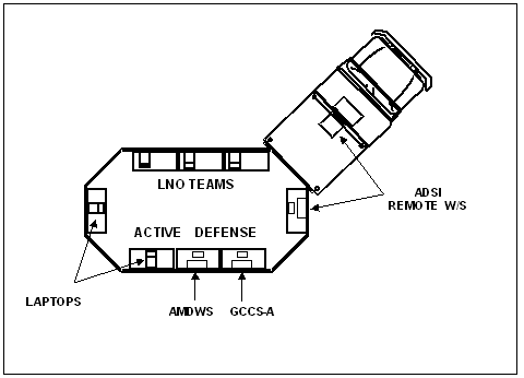
Figure A-2. Layout of Active Defense Cell
| |
This equipment is described below:
- The ADSI is a suite of automated communications equipment capable of receiving and transmitting messages in a variety of TADIL formats. This enables the ADSI to exchange air picture and other tactical information with joint and Army systems. The ADSI also receives intelligence information via the tactical information broadcast system (TIBS) and the tactical receive equipment and related applications data dissemination system (TDDS). This tactical and intelligence information is displayed on the ADSI tactical display and passed to other processors through a serial connection within the TOC, including the AMDWS. TIBS/TDDS data is passed to the AMDWS through the local area network (LAN).
- The AMDWS is the primary tool for monitoring and managing AMD operations. It receives air situational awareness from the ADSI, and ground situation and intelligence information from the maneuver control system (MCS), all source analysis system remote work station (ASAS RWS) and other sources. The AMDWS maintains a comprehensive database of the tactical situation and also provides mission-planning capabilities to overlay sensor coverage, weapons coverage, airspace control measures, threat locations, and planned unit positions.
- The GCCS-A receives air and missile situational awareness, joint friendly force information, intelligence information, and weather data from a variety of sources. The cell uses this information to keep track of the TM situation and the locations of friendly forces so the forces can quickly be warned in the event of a TM or NBC attack.
- The laptop computers are used for both operational and administrative purposes and provide connectivity via the SIPRNET to AAMDC staff and LNOs and other SIPRNET users.
|
ATTACK OPERATIONS CELL
| |
A-3. The attack operations cell and its automated equipment are shown in Figure A-3. This equipment includes the automated deep operations coordination system (ADOCS), the advanced field artillery tactical data system (AFATDS), the all source analysis system remote workstation (ASAS RWS), the generic area limitation environment (GALE), the joint services workstation (JSWS), and laptop computers. |
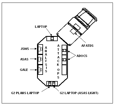
Figure A-3. Layout of Attack Operations Cell
| |
This equipment is described below:
- The ADOCS is an integrated set of automated tools used for mission planning, coordination, analysis, and data management. It displays a variety of data including friendly and enemy unit locations, air corridors, restricted fire areas, and operational graphics. It is used to submit TM target nominations to the DOCC and provide friendly artillery and fire support coordination measure (FSCM) situational awareness to the attack operations cell and LNOs.
- The AFATDS is an automated workstation that displays friendly artillery database information and facilitates management of fire support operations by processing fire mission requests and air support mission requests. It is used to submit TM target nominations to the DOCC and provide friendly artillery and FSCM situational awareness to the attack operations cell and LNOs.
- The ASAS RWS receives and correlates data from strategic and tactical intelligence sensors and sources. This data includes electronic, signal, imagery, and human intelligence. The RWS displays the enemy and friendly situations and includes tools that can be used to perform IPB, situation and event analysis, and target planning.
- The GALE is an automated workstation that contains a comprehensive terrain database. It is capable of analyzing terrain and predicting the most probable locations of enemy launch areas, forward operating bases, hide sites, and support areas. It is also capable of modeling the movement of enemy mobile launch platforms and predicting where they are going, what roads they will be using and the time required to reach their destinations.
- The JSWS is an automated workstation that receives surveillance imagery from the joint surveillance and target attack radar system (JSTARS) platforms that are imaging fixed targets or tracking enemy mobile launch platforms. The JSWS displays this imagery, enabling the operator to provide accurate targeting information, including fixed and mobile target locations, speed, target classification, and direction of movement.
- The laptop computers are used for operational, administrative, and intelligence information dissemination purposes and provide connectivity via the SIPRNET to AAMDC staff and LNOs and other SIPRNET users.
|
PASSIVE DEFENSE CELL
| |
A-4. The passive defense cell and automated equipment within the cell are shown in Figure A-4. This equipment includes not only the passive defense equipment but also equipment belonging to the G2 current operations section. The passive defense equipment includes the global command and control system-Army (GCCS-A), the joint warning and reporting network (JWARN), the maneuver control system (MCS), the worldwide origin and threat system (WOTS), and laptop computers. The G2 equipment includes the ASAS RWS and the airborne broadcast intelligence system (ABIS). |
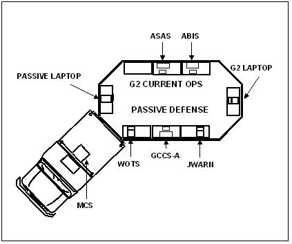
Figure A-4. Layout of Passive Defense Cell
| |
This equipment is described below:
- The GCCS-A receives air and missile situational awareness, joint friendly force information, intelligence information, and weather data from a variety of sources. The cell uses this information to keep track of the TM situation and the locations of friendly forces so the forces can quickly be warned in the event of a TM or NBC attack.
- The JWARN is an automated workstation linked via tactical communications to NBC detection devices in the theater. It provides comprehensive NBC warning, reporting, and analysis capabilities and can display the type of event, time of the event, type of burst/agent, area of contamination, downwind hazard, and units affected.
- The WOTS receives reports of TM launches from theater and national intelligence sources. It correlates these reports and displays event numbers, the numbers of missiles launched, the predicted impact ellipses, and the estimated impact times.
- The MCS provides incoming missile warning information and a comprehensive view of friendly forces information. It forwards ground situation and intelligence information to the AMDWS. It is used in the PD cell primarily as a backup to the GCCS-A, JWARN and WOTS systems.
- The passive defense laptop computer hosts software that can be used to predict the ground effects of a TM warhead burst and also determine which friendly units will be affected by NBC agents. Another laptop is used for operational and administrative purposes and has SIPRNET connectivity.
- The ASAS RWS receives and correlates data from strategic and tactical intelligence sensors and sources, and includes tools that can be used in IPB, situation/event analysis, and target planning. See AO cell discussion in paragraph A-3.
- The ABIS provides a three-dimensional picture of the battlespace that includes real-time, multispectral high-resolution intelligence imagery, threat following, and threat displays. It provides a detailed picture of the enemy situation, the location of enemy launch sites and ellipses of impact points. The system also provides a simultaneous display of up to three digital maps and/or imagery products.
|
G3 PLANS AND COMMUNICATIONS CELL
| |
A-5. The G3 plans and communications cell and its automated equipment are shown in Figure A-5. This equipment includes the ADSI, the AMDWS, the commander's analysis and planning system (CAPS), the contingency theater automated planning system (CTAPS) and two laptop computers. |
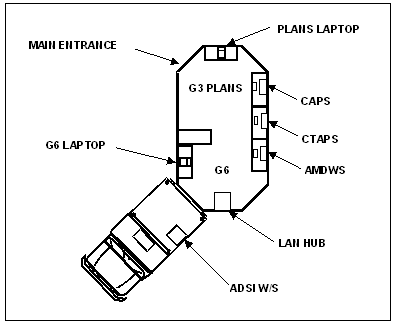
Figure A-5. Layout of G3 Plans and Communications Cell
| |
This equipment is described below:
- The ADSI provides timely air and ground pictures for use in planning current and future operations. See description in paragraph A-2.
- The CAPS is an automated system used to plan and optimize defenses. It is capable of modeling defensive coverages and running iterative attack scenarios to determine if coverages and levels of protection are satisfactory. With added software it can also exchange overlays and other information with joint systems. CAPS will eventually be replaced by the joint defense planner.
- The CTAPS is an automated system used to receive the air tasking order (ATO), airspace control order (ACO), and special instructions directly from the JFACC staff. It allows the G3 cell to maintain ATOs/ACOs and interact with joint force planning. CTAPS will eventually be replaced by the theater battle management core systems (TBMCS). The ATO and ACO will be received from TBMCS by AMDWS.
- The laptop computers are used for both operational and administrative purposes and provide connectivity via the SIPRNET to AAMDC staff and LNOs and other SIPRNET users.
|
PERSONNEL AND LOGISTICS CELL
| |
A-6. The personnel and logistics cell and its automated equipment are shown in Figure A-6. This equipment currently includes two AMDWS and two laptop computers. Also shown are two global combat support systems-Army (GCSS-As), which will eventually replace the AMDWS. |
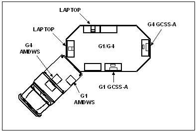
Figure A-6. Layout of Personnel and Logistics Cell
| |
This equipment is described below:
- The AMDWS is used by the G1/G4 cell to manage personnel and logistics functions. It provides an automated rollup for submitting personnel reports, unit reports, and daily summaries.
- The GCSS-A is an automated system that provides timely situational awareness and force projection information to allow the G1/G4 staff to support current and future operations. It is capable of rapidly collecting, storing, analyzing, and disseminating critical personnel, logistics, medical, and financial information and is used in planning and decision-making activities.
- The laptop computers are used for operational, administrative, and logistics purposes and provide connectivity via the SIPRNET to AAMDC staff and LNOs and other SIPRNET users.
|
COMMAND GROUP
| |
A-7. The command group work area is shown in Figure A-7. It contains workspace and facilities for the AAMDC commander, the chief of staff, and the battle captain. |
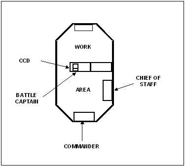
Figure A-7. Layout of Command Group Work Area
| |
The battle captain's workstation includes the central communications display (CCD), which is used to direct and coordinate AAMDC operations. The CCD is linked via the LAN to other workstations within the TOC. It allows the battle captain to selectively view other displays including the ADOCS, GALE, ADSI, AMDWS, ASAS RWS, and MCS. It also allows him to communicate with operators of other displays to facilitate coordination of TOC operations. |
COMMUNICATIONS EQUIPMENT
| |
A-8. The following communications equipment is included in the AMDPCS:
- Digital Small Switch (DSS). The DSS is a 16-port digital switch that allows integrated service telephones to intercommunicate within the AMDPCS. This reconfigurable function facilitates voice communications by conferencing between system operators and the battle and assistant battle captains. It can also incorporate commercial lines, radios, and external communications equipment and may be operated up to and including the SECRET level.
- Integrated Services Telephone (IST). The IST allows users to connect to a complete array of communications systems (radio nets and commercial telephone systems) and other AMDPCS equipment operators. Each phone is equipped with connectors for two push-to-talk (PTT) headsets or handsets. They include 40 preset lines and include functions such as call hold, call transfer, and ringer/headset volume.
- TSEC/KY-68 Digital Secure Voice Terminal (DSVT). The ruggedized terminal is used for encrypting/decrypting voice traffic and provides secure digitized data traffic. It includes a push-to-talk handset and operates as a full duplex voice/data subscriber terminal and is switch selectable for 16 or 32 kilobytes per second.
- MDA-38 DSVT Interface Box. The MDA-38 is an eight-channel, digital, non-secure voice terminal emulator that interfaces MSE and TRI-TAC circuits to the DSS switch. It allows IST users on the DSS switch to talk to users on MSE/TRI-TAC networks without having to switch to a different type of telephone terminal.
- Patch Panels. The communications patch panel (CPP) allows routing of external and internal signals and provides flexibility in configuring interconnections between equipment and routing around line failures. The DSS patch panel complements the CPP by allowing four and two wire circuits such as radios and telephone lines to be directly interfaced to the DSS.
- Line Termination Unit (LTU). The LTU can provide up to 18 channels and is utilized as a multiplexer/demultiplexer. It functions in support of receiver/transmitter MSE communications.
- UHF SATCOM Radio. The radios are used for satellite and line-of-sight communications operating the 225- to 400-megahertz UHF band. It provides data and secure/nonsecure voice capability.
- AN/GRC-138 Transceiver. The AN/GRC-138 receiver/transmitter is a high frequency/very high frequency (HF/VHF) system that operates with a frequency 1.6 to 60 megahertz. The built-in modem allows 2400 or 300 bytes per second (data communication.
- TSEC/KY-99 Trunk Encryption Device. The TSEC/KY-99 provides the secure voice for and is collocated with selected UHF SATCOM radios.
- Digital Nonsecure Voice Telephone (DNVT). The DNVT is a ruggedized unsecure data and voice field telephone that interfaces with MSE.
- Secure Telephone Unit (STU) III. The STU III provides a secure voice and data telephone capability between commercial networks. It operates over most existing telephone networks and has selectable specific modes of secure operation.
- AN/GSQ-240 JTIDS 2M Terminal/Antenna. JTIDS is the primary interface means for radio frequency (RF) TADIL-J information to be received from and transmitted into the joint data network (JDN). The terminal utilizes embedded crypto to process secure digital data information such as situational awareness, friendly force management, and targeting information. It operates in the bandwidth from 960 to 1215 megahertz.
|
TACTICAL TELEPHONES
| |
A-9. Tactical telephone users are shown in Figure A-8. These users may be physically located in the TOC or in a fixed facility in the vicinity of the TOC. |
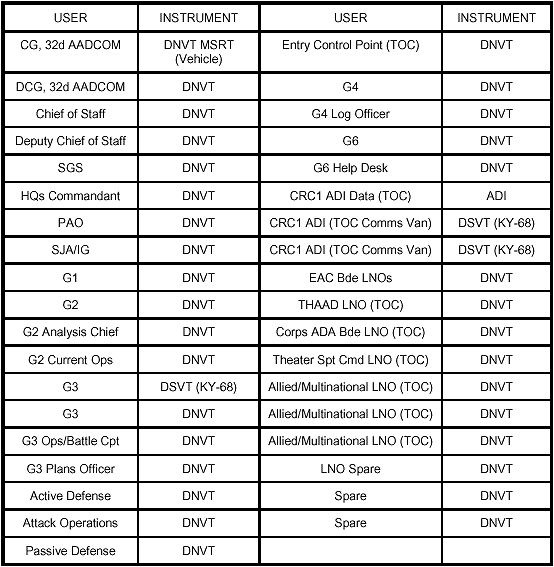
Figure A-8. Tactical Telephone Users
LNO EQUIPMENT AND SUPPORT
| |
A-10. Figure A-9 shows the equipment used by LNOs. It also summarizes LNO support requirements. |
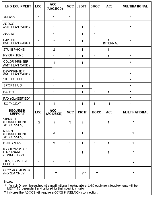
Figure A-9. LNO Equipment and Support Requirements
ANCILLARY EQUIPMENT
| |
A-11. Ancillary equipment, shown in Figure A-10, includes three HMMWV support vehicles, a communications security (COMSEC) van, two deployable rapid assembly shelters (DRASH) utilities shelter transporter (UST) trailers, two 35 kilowatt power generators, and eight equipment storage containers. |
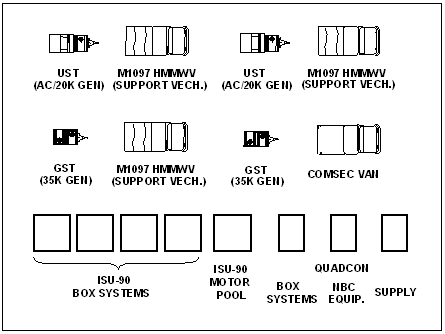
Figure A-10. AAMDC Ancillary Equipment
| |
This equipment is described below:
- The HMMWV support vehicles are used to transport the UST trailers, power generators, and other support equipment. The UST trailers each contain an integrated environmental control unit (ECU), electrical generator and power panel. When deployed, the ECU provides air-conditioning/heating for the AMDPCS shelters. The cargo area at the rear of each UST trailer is used to transport the DRASH shelters.
- The COMSEC van is used for secure storage and to transport one of the 35 kilowatt generators.
- The 35 kilowatt generators, along with the 20 kilowatt generators on the UST trailers, provide the electrical power required to run the AMDPCS during operations.
- The storage containers are used to store a variety of equipment and supplies required to support AAMDC operations. The containers are air lifted into the theater of operations and transported to the operational site using nonorganic transportation facilities.
|
|
NEWSLETTER
|
|
Join the GlobalSecurity.org mailing list
|
|
|


