

Chapter 4
Multichannel SHF System
a. Multichannel TACSAT terminals provide a reliable communications system. These terminals provide range extension for the area communications system.
b. The multichannel TACSAT systems use the DSCS II or DSCS III satellite and operate in the 7.25 to 8.4 GHz frequency range. The Army, Air Force, and Marine Corps operate these terminals. The Army and Marine Corps use the AN/TSC-85( )/93( ) while the Air Force uses the AN/TSC-94A/l00A. These terminals are compatible with Tri-Service Tactical Communications (TRI-TAC) and Mobile Subscriber Equipment (MSE) systems. These multichannel TACSAT terminals use FDMA. Therefore, centralized frequency selection and uplink power control are required.
a. Theater through brigade level commanders, special contingencies, and selected divisions use tactical multichannel satellite systems to support Army mission requirements. These systems were developed to augment existing terrestrial multichannel communications systems.
b. Multichannel satellite systems are designed primarily for trunking. Consider these factors when selecting a link requirement for multichannel TACSAT terminals:
- Criticality of the link to tactical command and control and the availability of other primary or supporting transmissions means.
- Ground range over which the link must be operated in various scenarios.
- Responsiveness and flexibility required with respect to siting and system reconfiguration.
- Link survivability requirements.
c. Consider these factors when deploying the AN/TSC-85( )/93( )s:
- Equipment capabilities.
- Network configuration.
- System descriptions.
d. The AN/TSC-85( ) TACSAT terminal is housed in a modified S-280 shelter. It operates with an organic AS-3036/TSC (8-foot diameter) antenna which is moved in an antenna pallet transit frame (APTF). It may also operate with either the nonorganic AS-3199/TSC (20-foot diameter) antenna or the OE-361(V)/G quick reaction satellite antenna (QRSA). All three antennas operate with DSCS satellites.
(1) The four curbside racks inside the shelter contain the baseband (multiplexing or demultiplexing) equipment. The four racks on the roadside of the shelter contain the modems and intermediate frequency (IF) or RF assemblies. The electronic equipment can operate in a nuclear, biological, chemical (NBC) environment.
(2) Each part of the satellite terminal equipment (shelter and APTF) is transportable by road, air (C-130, C-141, C-5A, or helicopter), rail (flatbed), and sea (ship). For the shelter to be mobile by rail or air, the M-720 mobilizer (nonorganic) must be used.
(3) Terminal setup time for a team using the organic AS-3036/TSC is 30 minutes (three-person crew).
e. The AN/TSC-85( ) TACSAT terminal (nodal terminal) provides the following:
- Transmission of a single SHF uplink carrier with up to 48 channels of voice and/or digital data (internally multiplexed). An additional 48 channels of voice and/or digital data from a remote (externally) multiplexed source may also be transmitted.
- On the downlink side, four carriers can be received, demodulated, and switched to user interfaces.
- Fully independent operation from a 15-kilowatt, three-phase, five-wire diesel generator or compatible commercial power.
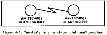
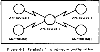
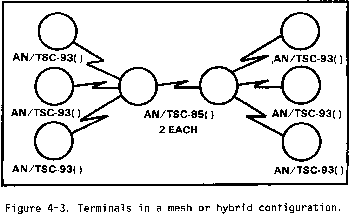
- Link with a nodal or non-nodal terminal in the point-to-point, hub-spoke, and mesh or hybrid mode. (See Figures 4-1 through 4-3.)
- Links with DSCS gateway terminal to provide Defense Communications System(DCS) entry.
f. A modified S-250 shelter houses the AN/TSC-93( ) TACSAT terminal. It operates with the AS-3036/TSC (8-foot diameter) antenna.
(1) The shelter is normally transported on the bed of a 2 1/2-ton truck with the disassembled 8-foot antenna on an M1028 commercial utility cargo vehicle (CUCV). Each truck tows a trailer-mounted diesel generator or power unit.
(2) Three curbside racks inside the shelter contain the baseband (multiplexing or demultiplexing) equipment. Three racks on the roadside of the shelter contain the modem and IF or RF assemblies.
(3) Each part of the satellite terminal equipment is transportable by road, air (C-130, C-141, C-5A, or helicopter), rail (flatbed), and sea (ship).
g. The AN/TSC-93( ) TACSAT terminal (non-nodal terminal) provides the following:
- Transmission of an SHF uplink carrier with up to 24 channels of voice and/or digital data (internally multiplexed).
- Link with a non-nodal terminal in the point-to-point or a nodal terminal hub-spoke mode.
- On the downlink side, can receive, demodulate, and switch a single SHF carrier via the demultiplexing equipment to the user interface.
- Fully independent operation from a 10-kilowatt, three-phase, five-wire diesel generator or compatible commercial power.
- Link with DSCS gateway terminal to provide DCS entry.
a. Limitations. Channel capacity on DSCS II and DSCS III satellites limits the number of TACSAT terminals that can operate at any one time. This number varies depending on several factors. These factors can include the type of terminal, number of channels, condition of terminals and satellite, size of antenna, and location of terminals within satellite footprint. These factors and others (for example, weather) affect how many terminals can use a satellite. For these reasons it is not possible to give a clear-cut number of terminals that can be operated at any one time. Unfortunately, there is not enough space segment to satisfy all the users. It should be stressed that DSCS II and DSCS III satellites support Army, Navy, Air Force, Marine, and other DOD/non-DOD users. The satellite channels on DSCS II and DSCS III are JCS assets and therefore not dedicated to any particular service.
b. Division.
(1) The divisions receiving multichannel TACSAT terminals are selected based on their operational areas, terrain, and distance considerations. The signal battalion installs, operates, and maintains the AN/TSC-85( )/93( )s.
(2) In selected divisions, five multichannel TACSAT terminals provide extended distance connectivity. Division main and division support command (DISCOM) use one
AN/TSC-85( ) each. One AN/TSC-93( ) is deployed to each of the three maneuver brigades. This is at the commander's discretion. An AN/TSC-85( ) at division main might terminate links from each maneuver brigade and DISCOM. During division main displacements, the terminal at DISCOM acts as the hub.
c. Corps. In the corps, two AN/TSC-85( )s and four AN/TSC-93( )s are pooled to provide support based on the general support (GS) concept. Terminals in support of corps are used for various missions such as restoration of critical links, out of sector operations, and deep operations. This concept has been developed based on the range extension capability of the MSE system. The corps signal brigade installs, operates, and maintains the AN/TSC-85( )/93( )s.
d. Contingency corps.
(1) AN/TSC-85( )/93( )s are distributed to the contingency corps based on their mission. The corps signal brigade installs, operates, and maintains the AN/TSC-85( )/93( )s.
(2) In the contingency corps, five AN/TSC-85( )s and eight AN/TSC-93( )s provide a low capacity multichannel (6/12 channels) range extension capability, independent of terrain and siting restrictions. It provides links from corps main and forward CPs to corps support command (COSCOM), the subordinate divisions, and other attached units.
e. Echelons above corps (EAC).
(1) At EAC, multichannel TACSAT provides connectivity between key EAC headquarters. EAC has been provided six AN/TSC-85( )s and ten AN/TSC-93( )s based on distance, terrain, criticality of links, and the need to augment LOS relays.
(2) TACSAT provides connectivity between major Army and combined commands in Europe and Korea.
f. Contingency support.
(1) For Army and JCS crisis contingency support missions, AN/TSC-85( )/93( )s are allocated to a TACSAT company, table(s) of organization and equipment (TOE) 11603. They deploy in support of Army and JCS contingency missions worldwide. This unit uses M-720 mobilizers for its AN/TSC-85( )s. The USAISC installs, operates, and maintains the AN/TSC-85( )/93( )s.
(2) The contingency corps area of operations is normally much larger than a doctrinal corps and requires augmentation. Three AN/TSC-85( )s and six AN/TSC-93( )s are allocated to the 235th Signal Detachment. They augment the contingency corps and Army contingency missions. This unit is also authorized M-720 mobilizers for its AN/TSC-85( )s.
a. USARSPACE RSSC GMF managers control and manage the TACSAT communications SHF multichannel terminals. These managers are collocated with the DCA elements at DCA-Europe, DCA-Pacific, and DCA-Washington. The GMF managers are the theater Commander in Chief's (CINC) resource managers and interface to the DSCS and DCA. DCA is the overall DSCS system manager and technical director providing satellite resources to the GMF managers.
b. Communications control matches resources against requirements. It occurs at all levels of the control and management structure. The TACSAT multichannel terminals use the DSCS space system which includes the DSCS II and DSCS III satellites. The availability of resources is considered in all cases as in the single-channel TACSAT program. Emphasis is also placed on mission and organizational priorities in accordance with JCS MOP 178.
c. The process for GMF satellite control, management, and access flow follows the path outlined below.
- Receives the SAR from the CSPE.
- Coordinates with DCA for added resources.
- Develops alternate plans and coordinates with the CSPE if SARs cannot be met due to resource restrictions.
- Initiates and transmits an SAA to the CSPE or denies access based on available resources.
- Is the system manager and technical director for the DSCS.
- Allocates the resources available.
- Adjudicates resource requirements between GMF and DSCS users.
- Is under the operational control (OPCON) of the GMF manager.
- Has OPCON of all GMF TACSAT terminals.
- Uses resources within the GMF allocation and the SAA.
- Is the satellite network controller (SNC).
- Has overall control of the DSCS satellite.
- Monitors the GMF subnetwork for violations and notifies the GNC for correction.
(1) Communications system planning element (CSPE). The CINC'S CSPE planner coordinates, consolidates, and prioritizes the user elements satellite requirements within his theater. He submits satellite access requests (SARs) to the GMF managers. On approval he receives the satellite access authorization (SAA) that provides operation orders (OPORDs) or operation plans (OPLANs) to the terminal operators.
(2) RSSC GMF manager. The RSSC GMF manager--
(3) DCA. The DCA--
(4) JCS. The JCS adjudicates differing resource requirements of the CINC which cannot be resolved between the CSPE, the GMF manager, and the DCA due to resource limitations.
(5) GMF network controller (GNC). The GNC--
(6) The Defense Satellite Communications System Operations (DSCSOC) controller. The DSCSOC controller--
a. Capabilities. The AN/TSC-85( )/93( ) terminal configurations allow digital interface with TRI-TAC equipment and MSE. They also provide limited capability for analog input and an ECCM capability for operation in a stressed environment. The Product Improvement Program incorporates replacing the TD-660s, TD-1065s, TD-1069s, KG-27s, and adding the antijam/control modem (AJ/CM), low rate multiplexer (LRM)/TD-1389, and KG-94A. Upon completing the program, the modified terminals will be redesignated as AN/TSC-85B/93B.
b. AN/TSC-85( ). Four TD-660s and TD-1065s will be replaced by four TD-1389s to function as the multichannel multiplexer for unstressed/clear mode communications. Two CV-1548 telephone signal converters and two MX-9635 echo suppressors will be removed and two CV-1548s and MX-9635s will remain. These two unit pairs will remain to support use of two-wire telephones. Four TD-1069s, or their reserved cavity locations, will be removed and replaced by four TD-1389s to function primarily as a multiplexer for the AJ/CM, or alternately as a submultiplexer into another TD-1389. Eight TD-1389s will be installed in each AN/TSC-85( ). Sufficient crosspatch capability will be provided to permit any TD-1389 to function in any role. Baseband patching will be available to provide access to all baseband ports on the shelter entry panels. This will allow the individual channels of the CV-1548/MX-9635 to be patched into any user channel as required. In addition, four KG-27s will be replaced by four KG-94As to provide bulk encryption for four unstressed/clear mode multichannel groups. A nodal terminal AJ/CM will be installed. It will provide an antijamming communications channel and will replace the FM control orderwire. Four STU-III/equivalent 2.4 kbps secure voice devices will be added to provide an AJ/CM stress mode secure voice capability. All other items in the terminal will remain the same.
c. AN/TSC-93( ). Two TD-660s and two TD-1065s will be replaced by one TD-1389 to function as the multichannel multiplexer for unstressed/clear mode traffic. One CV-1548 and one MX-9635 will be removed and one of each will remain to support use of two-wire telephones. One TD-1069, or its reserved location, will be removed and replaced with one TD-1389 to function primarily as a multiplexer for the AJ/CM or alternately as a submultiplexer into another LRM/TD-1389. A total of two LRM/TD-1389s will be installed. Sufficient crosspatch capabilities will be provided to permit any TD-1389 to function in any role. Baseband patching will be able to access all baseband ports on the shelter entry panels. This will allow the individual channels of the CV-1548/MX-9635 to be patched into any user channel as required. In addition, two KG-27s will be replaced by one KG-94A to provide bulk encryption for one unstressed multichannel group. A non-nodal terminal AJ/CM will be installed. This AJ/CM will provide an antijamming communications channel and replace the FM control orderwire. One STU-III/equivalent will be added to the AN/TSC-93( ) to provide an AJ/CM stress mode secure voice capability.
d. Differences. The main differences in tactical multichannel terminal configurations are the types and amount of redundant equipment in the configuration and the terminal's communications capability. The equipment is configured in either a nodal (hub) or non-nodal (spoke) configuration. A nodal terminal can be configured to operate with up to four terminals in a multipoint operation. Any two terminals, either nodal or non-nodal, can be configured to provide a point-to-point requirement.
4-6. Antijamming and ECCM Techniques
a. AJ/CM is a family of spread-spectrum modem equipment designed to provide GMF TACSAT terminals with an ECCM capability for operation in a stressed environment. The normal mode of operation for high capacity links in a benign or nonstressed environment uses the current biphase shift keying/quadraphase shift keying (BPSK/QPSK) modems and FDMA link accesses.
b. The family of modems consists of a network control terminal (NCT), a nodal terminal (NT), and a non-nodal terminal (NNT). The AJ/CM provides a lower capacity 75 bps and 32 kbps communications capability and an antijamming control orderwire.
(1) NCT modem. The AN/MSQ-114/FSQ-124 satellite control and monitoring systems use the NCT modem. It is made up of two chassis assemblies: the MD-1133 and the OX-63 coder group.
(a) The MD-1133 network control unit (NCU) interfaces with the terminal frequency reference and distributes time and frequency to the NCT internally. The NCU also provides the NCT modem modulation/demodulation functions. User commands initialize and control NCU hardware elements to perform major NCT operations or processing. The NCT contains bus logic to control an externally-programmable down-converter. The NCT also provides modem and network status monitoring and provides status and messages to the NCT operator.
(b) The OX-63 coder group, TRANSEC, 4-channel unit houses four KGV-9 TRANSEC modules, associated interface circuits, and the necessary power supplies.
(2) NT modem. Army and Marine AN/TSC-85As and Air Force AN/TSC-100As use the NT modem. It is made up of three chassis assemblies: the MD-1131 modem, the MD-1132 communications unit, and the OX-64 coder group.
(a) The MD-1131 modem contains a beacon demodulator, a 75 bps critical control circuit (CCC), and a variable data rate 75 bps to 32 kbps link communications circuit (LCC). This modem also contains all operator controls.
(b) The MD-1132 communications unit contains three LCCs. These circuits provide the three links required for hub operation.
(c) The OX-64 coder group, TRANSEC, 10-channel unit houses ten KGV-9 TRANSEC modules, associated interface circuits, and the power supplies.
(3) NNT modem. Army and Marine AN/TSC-93As, Air Force AN/TSC-94As, and selected satellite fixed station gateway terminals use the NNT modem. It is made up of two chassis assemblies: the MD-1131 modem and the OX-63 coder group.
(a) The MD-1131 modem is identical to the NT modem.
(b) The OX-63 coder group, TRANSEC, 4-channel unit is identical to the NCT modem.
Data entry requirements for the operator of a multichannel TACSAT terminal AN/TSC-85( )/93( ) consist of information (data) extracted from the SAA by the CSPE and included in either the mission OPLAN or the exercise OPORD. This information takes the form of--
- Operating frequencies. (May not apply until SAA is received.)
- Data rates.
- Transmit power. (May not apply until SAA is received.)
- Mission configuration.
- Terminal identification.
- Terminal locations.
- Satellite "look angles" (azimuth and elevation). (May not apply until SAA is received.)
- Mission start and stop time.
- Priority of communications.
b. The CSPE extracts this information from the OPLAN/OPORD and provides it to the terminal operator. The data entries are categorized and differentiated between operating parameters, network characteristics, and configuration routines. Figures 4-4 and 4-5 are examples of data entry sheets.


- Transmit frequencies.
- Receive frequencies.
- Transmit power.
- Terminal locations.
- Satellite "look angles" (azimuth and elevation).
- Data rates.
- Network configurations.
- Terminal call sign.
(1) Operating parameters include--
(2) Network characteristics include--
|
NEWSLETTER
|
| Join the GlobalSecurity.org mailing list |
|
|
|