

Go to report table of contents
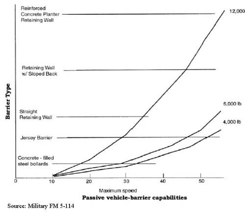
Figure E-1. Line chart showing passive vehicle barrier capability by barrier type and speed. Source: Military FM 5-114.
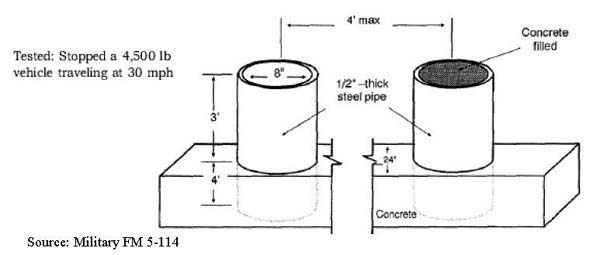
Figure E-2. Concrete Filled Steel Bollards
Figure E-3. Jersey Barrier
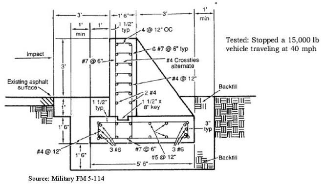
Figure E-4. Straight Retaining Wall
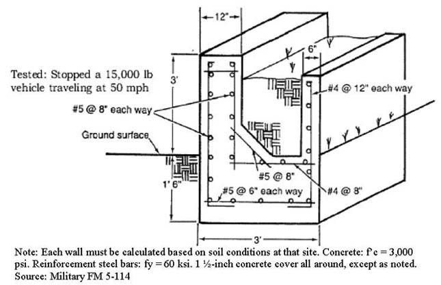
Figure E-5. Sloped-Back Retaining Wall
Figure E-6. Reinforced Concrete Planter/Retaining Wall
Figure E-7. Active Barrier Test Results and Examples
Table E-1. Tested Barrier Design - Test Result
Appendix E. Vehicle Barrier Selection and Implementation Considerations
This appendix provides details on:
- Barrier selection considerations
- Implementation issues in selecting barriers
- Crash performance data for active and passive barriers
Barrier Selection
Threat /Desired Use
Select the level of security that is required for a particular facility based on a threat and vulnerability assessment. Barriers can be used to protect against several common aggressor tactics including: bombs in moving vehicle, bombs in stationary (parked) vehicle, or forced-entry attacks.
Degree of Protection/Crash Rating
Determine the degree of protection (range of physical restraint) required. To do this, knowledge of the setback, vehicle speed, vehicle approach angle, vehicle weight, and size of explosive package is required. Table E-1 lists test results of different types of active and passive barrier testing. For a list of specific make/models of Department of State (DOS) certified anti-ram vehicle barriers refer to http://www.statebuy.state.gov/compad/documents/CertifiedVehicleBarriersRevA-02-04-05.doc
Barriers are tested and certified to perform to specific Federal criteria (a specific level of anti-ram protection). In selecting barriers, it is important that transit agency security engineers consider the capabilities of these systems to protect against the threats specific to the facility. For crash-rated barriers, the weight and speed of the crashing vehicle are specified as well as the "allowed movement" of the barrier upon impact. There is a wide range of weights and speeds based on anticipated threat and physical approach.
Refer to the following documents for a list of standards and requirements that a potential product must satisfy to become qualified: Department of State (DOS) standard, SD-STD-02.01 (latest revision) - Specification for Vehicle Crash Test of Perimeter Barriers and Gates, and 12 FAH 5 - Foreign Affairs Handbook - Physical Security Handbook.
Source: Military FM 5-114
Passive vs. Active
Passive barriers can be used at entry points if traffic flow is restricted or rarely used. Passive barriers are normally used for perimeter protection.
Portability
What is involved if the barrier needs to be moved/repositioned? Some barriers are massive and heavy, requiring the use of heavy equipment for placement. Once placed, these barriers can only be moved by bringing in heavy lifting equipment, and cannot be quickly changed to allow access status for authorized vehicles. If portable, how easy is the barrier to carry, transport, stack, store, and put together/interlock? What is the time needed to deploy?
Width / Load Capacity
Are the appropriate widths available to fully protect while allowing passage of almost every type of vehicle?
Barrier Activation Mode
For high traffic entries, vehicle barriers are normally open and closed only upon detection of a threat. For "low flow" or "high threat" conditions, barriers are normally closed in order to stop vehicle flow and are lowered only after authorization has been approved (this is the more secure mode). For automated vehicle access systems the barrier should automatically return to the closed/protected position once a sensor has detected vehicle passage and should not allow tailgating. Whether the barrier can be locked in the up or down position should also be noted.
Access Control Options
Control for vehicles can include either automated or semi-automated access control, or manual access control. In automated or semi-automated access control, the driver of the vehicle will use a machine-readable device to open the barrier, or present suitable identification via CCTV to a remote monitoring station. In a manually controlled situation, a security person is stationed at the point of entry to monitor access. Ensure that the barrier selected can be operated by a variety of control systems to satisfy your current and future needs, including needs for card and proximity readers, for keypads, for inductive loops, and for intercom. The ability to operate the system locally and/or by remote control should also be considered in the selection process.
Compatibility with Other Security Components
Active barriers should be compatible with other security equipment installed at the site (IDS, CCTV, etc.) and with the available power source.
Operation
Barriers can be operated manually, electrically, pneumatically, or hydraulically. Can the system operate individually and in groups? Is there a manual override? Can the system work in manual operation in the event of power failure? Barrier direction should be instantly reversible at any point in its cycle from the control station(s).
Consider Options / Alternate Approaches
Options exist for reconditioning, refurbishing, or covering existing barriers. It is also possible to initiate an evolutionary plan in which the perimeter is progressively covered or where the entire perimeter is covered with something that can evolve to a higher level of protection over time. The difficulty of making site modifications (e.g., relocating truck deliveries away from the protected facility) that would to make vehicle barrier unnecessary or a lesser-rated barrier acceptable should also be assessed.
Barricade Speed / Response Time
The barrier system must contain sufficient time delay after activation to allow the vehicle to enter or exit the parking area.
Cycle Time/Pass-through Rates
Ensure that the device pass-through rate is consistent with the desired vehicle processing (3 to 15 seconds is suitable for most inspection and identification station requirements).
Environment
Not all barriers will be suited to all locations. Barrier components may require protection from excessive heat/cold, dirt, humidity, sand, high water table, or require additional maintenance.
Reliability / Maintenance
Reliability is an important factor in selecting active barriers. Most manufacturers offer maintenance contracts. If a facility requires an active vehicle barrier, the company selected can provide adequate service. Will it require painting and is it resistant to corrosion? Know what, where, when, and how maintenance will be done. Evaluate the system's failure modes to ensure that the barrier will fail in the predetermined position (open or closed) based on the security and operational requirements. Backup generators or manual override provision are needed to ensure continuous operation during power failures or equipment malfunction. Reliability and maintainability data are available from most manufacturers.
Safety Options / Features
Active barrier systems are capable of inflicting serious injury, even when used for their intended purposes. Warning devices (visible colors and patterns, reflectors, lighting, warning lights, and safety signals) should be used to mark the presence of a barrier and enhance its visibility to drivers. Vehicle detector safety loops and road plates checkered for good traction can also enhance safety.
Mounting / Foundation Requirements
Consider the costs of sitework for mounting or foundations:
- Surface Mounted - quick installation in difficult locations such as parking structure ramps or areas with sub-surface drainage problems.
- Shallow Foundation - sub-surface conditions that negate extensive excavations and obviate the concerns of interference with buried pipes, power lines, and fiber optic communication lines; reduces installation complexity, time, materials, and corresponding costs.
- Sub Surface - can require extensive excavations and the need to work around buried pipes, power lines, and fiber optic communication lines.
Aesthetics
What range of visual dissonance is acceptable? An attractive appearance is usually desirable, but can contribute to the cost. The aesthetic components include color, texture, shape, and live material (plantings).
Liability
Liability issues resulting from death or injury due to normal operation or inadvertent use/ malfunction should be considered.
Budget
What range of financial resources is available? It is important to ensure that the total cost is anticipated in the preliminary planning stages. In addition to the actual cost of the barrier product, whether purchased or fabricated on site, there may be freight, placement, equipment rental, utility modification, site-work, clean up, or other related expenses. Reliability, availability, and maintainability requirements will affect the cost of the system.
Implementation Issues
- Plan appropriate space if vehicle inspections are to take place. Locate the inspection area at the appropriate standoff distance from the facility. If possible use separate entrances for employees, visitors, and deliveries. If this is not possible, multiple lanes (for employees and others) can help to maintain maximum employee traffic flow. Clearly mark visitor/delivery entrances and lanes.
- Place active barriers away from inspection areas to reduce the required guard reaction time.
- Locate barrier support equipment (e.g., hydraulic power, generator, etc.) on the secure side away from guard posts to lower the threat of sabotage and injury to security personnel.
- Tamper switches should be installed on all vehicle barrier access doors, controllers, and hydraulic systems. Tamper switches should be connected to a central alarm station.
- Mark active barriers once they are installed and channel pedestrian traffic away from the system.
- Design barriers installed in clear zones so that they will not provide a protective shield or hiding place.
- Consider the use of barriers to stop vehicles from entering the wrong way via exit lanes.
- Ensure that buttresses, counterweights, and road plates do not obstruct authorized pedestrian or vehicular traffic.
- Plan for the appropriate use of safety equipment, such as traffic lights, inset warning lights, appropriate signage ("stop", "no entry", or "warning"), and safety buffers. Use clear signage and traffic control lights with active barriers.
- Provide operator training to prevent injury, reduce liability, and prevent equipment damage caused by improper operation.
Crash Performance Data
The following diagrams showing crash performance data for a variety of passive and active barriers. Data is from Military Field Manual FM 5-114.
 |
|
Figure E-1. Passive Vehicle-Barrier Capabilities |
 |
|
Figure E-2. Concrete Filled Steel Bollards |
 |
|
Figure E-3. Jersey Barrier |
 |
|
Figure E-4. Straight Retaining Wall |
 |
|
Figure E-5. Sloped-Back Retaining Wall |
 |
|
Figure E-6. Reinforced Concrete Planter/Retaining Wall |
 |
|
Figure E-7. Active Barrier Test Results and Examples |
|
NEWSLETTER
|
| Join the GlobalSecurity.org mailing list |
|
|
|