

LESSON 3
| LESSON 3 | Systems and Accessories. |
| TEXT ASSIGNMENT | Reference Text AL0993, paragraphs 2.1-2.26. |
| LESSON OBJECTIVE | To enable you to recognize and describe the gas turbine engine fuel and oil systems and their components. |
| CREDIT HOURS | 2 |
Chapter 2
SYSTEMS AND ACCESSORIES
2.1. INTRODUCTION
This chapter introduces the fundamental systems and accessories of the gas turbine engine. Each one of these systems must be present to have an operating turbine engine. Section I describes the fuel system and related components that are necessary for proper fuel metering to the engine.
The second section discusses the theory and components of the lubricating system. Oil is the lifeblood of any engine. If the oil supply to the bearings should cease, within a matter of seconds the lubricating films would break down and cause scoring, seizing, and burning of the vital moving parts.
The third section tells of the ignition system used in the gas turbine engines and of various cockpit instruments used to measure engine performance.
Section I. Fuel Systems and Components
2.2. GENERAL
The fuel system consists of the fuel control, speed governors, fuel pumps, starting fuel nozzles, main fuel system flow divider, main fuel manifold, and vaporizing tubes or nozzles. Fuel is conducted between these components by flexible or rigid lines. The fuel system must supply clean, accurately metered fuel to the combustion chambers. All fuel systems have basically the same components; how these specific units do their jobs differs radically from one engine to another. Some systems incorporate features that are not necessary to the metering of fuel, such as fuel and oil heat exchangers, use of fuel pressure to operate variable inlet guide vanes, and compressor bleed mechanisms. It is the purpose of this section to illustrate typical fuel systems so that the reader may obtain some idea of the route of fuel and location of the components that make up the system. Figure 2.1 shows a typical schematic of a gas turbine engine fuel system.
2.3. FUEL CONTROLS
The principles and operation of fuel controls used on current engines are discussed in this paragraph. Depending upon the type of engine and the performance expected of it, fuel controls may range from simple valves to automatic computing controls containing hundreds of intricate parts.
Strictly speaking, a pilot of a gas-turbine-powered aircraft does not directly control his engine. His command over the engine corresponds to that of the captain of a ship who obtains engine response by relaying orders to an engineer below deck who, in turn, moves the throttle of the engine. But before he moves the throttle, he monitors certain operating pressures, temperatures, and rpm that are not apparent to the captain. The engineering officer then refers to a chart and computes a fuel flow or throttle change which will not allow the engine to exceed its operating limitations. If you think of the pilot as the captain of the ship, then think of the automatic controls as the engineer. They, too, monitor operating pressures, temperatures, and rpm, and make the necessary fuel and throttle adjustments.
Fuel controls can be divided into two basic groups: hydromechanical, and electronic. There are as many variations in controls as there are engines. Although each type of fuel control has its particular advantage, most controls in use today are hydromechanical. Some fuel controls are extremely complex devices composed of speed governors, servo systems, valves, metering systems, and sensing pickups.
This section limits discussion mainly to fuel control theory of the hydromechanical type. A schematic of one is shown in figure 2.2. A fuel control in the simplest form consists of a plain metering valve to regulate fuel flow to the engine. A hydromechanical fuel control consists of the following main components, but it is not limited to only these.
-
Pump to pressurize fuel.
-
Governors to control rpm.
-
Relief valves to protect the control.
-
Manual control systems (emergency control system).
-
Fuel shutoff valve.
Most modern fuel control units meter the flow of fuel by keeping the pressure drop or difference across the metering valve a constant value, while varying the orifice of the metering valve. Another way to control fuel is to keep the valve orifice a constant size and vary the pressure acting upon the fluid. The operation of a gas turbine requires that a number of variable conditions be given careful thought to provide for safe, efficient operation. Among these are engine rpm, acceleration, exhaust gas temperature (egt), compressor inlet temperature, compressor discharge pressure, and throttle or power control setting. All these conditions affect or are affected by fuel flow, which is increased only to the point where the limiting temperature is reached. As the engine accelerates and airflow through the engine increases, more fuel is added. If turbine inlet temperature were the only engine limitation, a temperature pickup sensing this temperature could be used. However, it is also necessary to avoid the operating range that would cause a compressor surge and stall. Because more than one factor limits engine operation, it is necessary to schedule the accelerating fuel in accordance with a combination of these factors. Because turbine engine compressors are susceptible to surges and stalls, a control with a longer acceleration time is used than is needed for a reciprocating engine. This acceleration time is known as a "lag," and the pilot must be aware of the time it takes the engine to accelerate and give him the power change he requires. Compressor discharge pressure or burner pressure is commonly used as the variable for these controls, since they vary both with engine speed and inlet air temperature. By evaluating these variable conditions, a fair indication of the amount of fuel which can be burned without exceeding engine limitations is obtained.
Two fuel control systems are discussed in the following subparagraphs.
![]() a. Automatic control system. The amount of fuel required to run the engine at rated rpm varies with the inlet air temperature and pressure. For example, it requires less fuel to run the engine on a hot day than on a cold day. To relieve the pilot of the necessity of resetting the power lever to compensate for changes in outside air temperature and pressure, a speed governor is used. A simple speed governor consists of flyweights balanced by a spring. When the engine is running unloaded, at rated speed, the metering valve is open only far enough to supply the small amount of fuel required. If a load is applied to the engine, the speed decreases. This decrease in rpm causes the flyweights to move in under the force of the spring tension and the fuel valve to open wider and admit more fuel. With the additional fuel, the engine picks up speed again, and, as the rated speed is reached, the flyweights move the fuel valve in the closing direction until the proper steady-state fuel flow is reached.
a. Automatic control system. The amount of fuel required to run the engine at rated rpm varies with the inlet air temperature and pressure. For example, it requires less fuel to run the engine on a hot day than on a cold day. To relieve the pilot of the necessity of resetting the power lever to compensate for changes in outside air temperature and pressure, a speed governor is used. A simple speed governor consists of flyweights balanced by a spring. When the engine is running unloaded, at rated speed, the metering valve is open only far enough to supply the small amount of fuel required. If a load is applied to the engine, the speed decreases. This decrease in rpm causes the flyweights to move in under the force of the spring tension and the fuel valve to open wider and admit more fuel. With the additional fuel, the engine picks up speed again, and, as the rated speed is reached, the flyweights move the fuel valve in the closing direction until the proper steady-state fuel flow is reached.
![]() b. Manual (emergency) control system. When the governor control switch in the cockpit is moved from the automatic position to the manual (emergency), a valve is actuated in the fuel control, and fuel is redirected to the manual system metering valve. The throttle in a helicopter is of the motorcycle twist-grip type. When the governor is in the automatic position the throttle is rolled full open and left there, with the fuel control making all fuel-flow changes automatically. If the automatic fuel control fails, the pilot switches to the emergency mode and takes manual control of the throttle, which is mechanically linked to the manual metering valve. The manual throttle control has no compensation for altitude or temperature, and it has no protection against an engine overspeed.
b. Manual (emergency) control system. When the governor control switch in the cockpit is moved from the automatic position to the manual (emergency), a valve is actuated in the fuel control, and fuel is redirected to the manual system metering valve. The throttle in a helicopter is of the motorcycle twist-grip type. When the governor is in the automatic position the throttle is rolled full open and left there, with the fuel control making all fuel-flow changes automatically. If the automatic fuel control fails, the pilot switches to the emergency mode and takes manual control of the throttle, which is mechanically linked to the manual metering valve. The manual throttle control has no compensation for altitude or temperature, and it has no protection against an engine overspeed.
Keep in mind that so far the discussion has been on principles of operation, and any specific fuel control may differ.
Main fuel pressure pumps for gas turbine engines generally have one or two gear-type, positive-displacement, high-pressure elements. Each of these elements discharges fuel through a check valve to a common discharge port. Thus, if one element fails, the remaining element continues to supply sufficient fuel for engine operation. On some engines, the fuel pump is built in to the fuel control. However, on other engines the fuel pump may be a separate component.
Fuel flows through an external line from the fuel control to the starting-fuel solenoid. During the starting sequence, the pilot actuates the start-fuel solenoid switch in the cockpit. The solenoid actuates the valve to the open position, then fuel flows through an external line to the start-fuel manifold. The start-fuel nozzles are attached to the manifold; the number of nozzles varies according to engine design. The nozzles introduce atomized fuel in the combustion chamber during the starting sequence. After the engine has attained a specified speed, the main fuel starts to flow automatically. After the engine is running on the main fuel system, the start fuel system is shut off. A starting fuel system is shown in Figure 2.3.
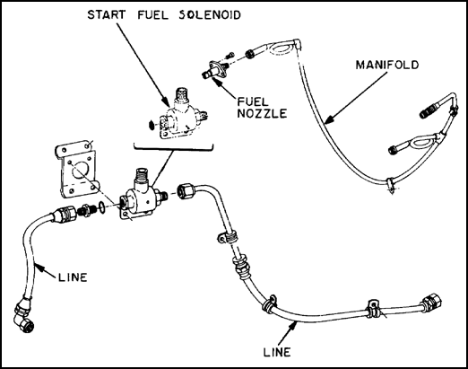
Figure 2.3. Starting Fuel System.
2.6. MAIN FUEL SYSTEM
Main fuel is delivered from the fuel control to the main fuel manifold assembly by external lines. The main fuel manifold delivers fuel to the fuel nozzles, which may be of the single or dual orifice injector type, designed to introduce the fuel into the combustion chamber. Some earlier engines use fuel vaporizer tubes in place of the more efficient fuel nozzles.
2.7. FUEL NOZZLES
On most gas turbine engines, fuel is introduced into the combustion chamber through a fuel nozzle that creates a highly atomized and accurately shaped spray of fuel suitable for rapid mixing and combustion. Most engines use either the simplex or the duplex nozzle. The exception to this is the Lycoming T53-L-11 engine which uses vaporizer tubes in place of fuel nozzles. Each type of nozzle is discussed in the following subparagraphs.
![]() a. Simplex nozzle. Figure 2.4 illustrates a typical simplex nozzle; as its name implies, it is simpler in design than the duplex nozzle. Its big disadvantage lies in the fact that a single orifice cannot provide a satisfactory spray pattern with the changes in fuel pressure.
a. Simplex nozzle. Figure 2.4 illustrates a typical simplex nozzle; as its name implies, it is simpler in design than the duplex nozzle. Its big disadvantage lies in the fact that a single orifice cannot provide a satisfactory spray pattern with the changes in fuel pressure.
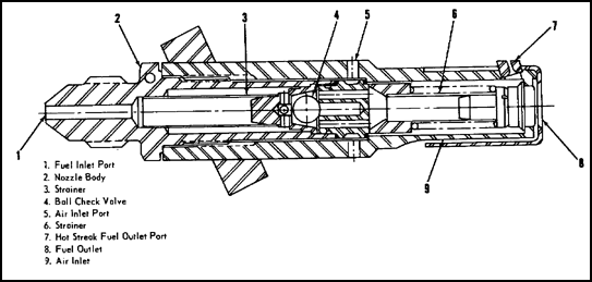
Figure 2.4. Simplex Fuel Nozzle.
![]() b. Duplex nozzle. Because the fuel-flow divider and the duplex nozzle work hand in hand, the description of these units is combined. The chief advantage of the duplex nozzle is its ability to provide good fuel atomization and proper spray pattern at all fuel pressures. For the duplex nozzle to work, there must be a fuel-flow divider to separate the fuel into low (primary) and high (secondary) pressure supplies. Single-entry duplex nozzles have an internal flow divider and require only a single fuel manifold, while, as shown in figure 2.5, dual-entry fuel nozzles require a double fuel manifold. The flow divider, whether self-contained in each nozzle, or installed separately with the manifold, is usually a spring-loaded valve set to open at a specific fuel pressure. When the pressure is below this value, the flow divider directs fuel to the primary manifold. Pressures above this value cause the valve to open and fuel is allowed to flow in both manifolds. A fuel flow divider is shown in figure 2.6.
b. Duplex nozzle. Because the fuel-flow divider and the duplex nozzle work hand in hand, the description of these units is combined. The chief advantage of the duplex nozzle is its ability to provide good fuel atomization and proper spray pattern at all fuel pressures. For the duplex nozzle to work, there must be a fuel-flow divider to separate the fuel into low (primary) and high (secondary) pressure supplies. Single-entry duplex nozzles have an internal flow divider and require only a single fuel manifold, while, as shown in figure 2.5, dual-entry fuel nozzles require a double fuel manifold. The flow divider, whether self-contained in each nozzle, or installed separately with the manifold, is usually a spring-loaded valve set to open at a specific fuel pressure. When the pressure is below this value, the flow divider directs fuel to the primary manifold. Pressures above this value cause the valve to open and fuel is allowed to flow in both manifolds. A fuel flow divider is shown in figure 2.6.
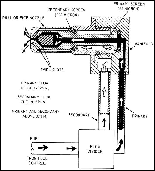
Figure 2.5. Dual Entry Duplex Nozzle.
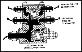
Figure 2.6. Fuel Flow Divider.
In addition, an air shroud surrounding the nozzle, as shown in figure 2.7, cools the nozzle tip and improves combustion by retarding the accumulation of carbon deposits on the face. The shroud also helps to contain the flame in the center of the liner.
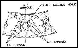
Figure 2.7. Air Shroud.
A word of caution; extreme care must be taken when cleaning or handling the nozzles, since even the acid on the fingers may corrode and produce a spray pattern which is out of tolerance.
![]() c. Vaporizing tube. Engines such as the Lycoming T53-L-11 use vaporizing tubes instead of injector nozzles. The vaporizing tube is a T-shaped, ceramic-coated pipe, whose exit faces upstream to the airflow. Figure 2.8 shows a vaporizing tube that is used on the T53-L-ll.
c. Vaporizing tube. Engines such as the Lycoming T53-L-11 use vaporizing tubes instead of injector nozzles. The vaporizing tube is a T-shaped, ceramic-coated pipe, whose exit faces upstream to the airflow. Figure 2.8 shows a vaporizing tube that is used on the T53-L-ll.

Figure 2.8. Vaporizing Tube.
Gas turbine engines may have several fuel filters installed at various points throughout the systems, one fuel filter before the fuel pump and one on the high-pressure side after the pump. In most cases the filter includes a relief valve set to open at a specified differential pressure (PSID) between inlet and outlet pressure. This gives the fuel a bypass if the filter becomes clogged from contamination.
More than one kind of filter is used on turbine engines. A paper cartridge filter is usually used on the low-pressure side of the pump. It uses a replaceable paper element, shown in figure 2.9, capable of filtering out particles larger than 100 microns, or about the diameter of human hair.
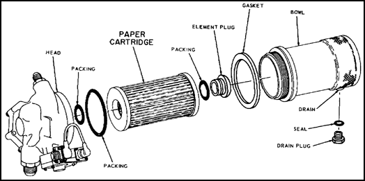
Figure 2.9. Paper Cartridge Fuel Filter.
A cylindrical screen filter is generally used where the fuel pressure is low. The filter is constructed of stainless steel wire mesh cloth and is capable of filtering out particles larger than 40 microns. Such a filter, shown in figure 2.10, may be cleaned, preferably ultrasonically, and reused.
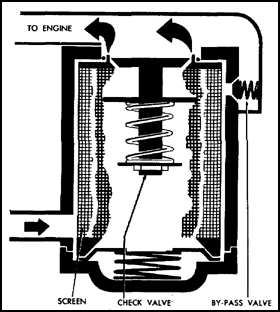
Figure 2.10. Cylindrical Screen Filter.
2.9. PRESSURIZING AND DRAIN DUMP VALVES
Until sufficient pressure is attained in the fuel control to compute the fuel flow schedules, flow to the main fuel nozzle is prevented by the pressurizing and drain dump valve. This valve also drains the fuel manifold at engine shutdown to prevent post-shutdown fires, and it traps fuel in the upstream portion of the system to keep the fuel control primed to permit faster starts.
All manufacturers install a combustion chamber drain valve in the combustion section. During normal engine operation this valve is closed. The drain valve is located at the lowest part of the combustion chamber. When the combustion pressure in the chamber drops below a specified minimum, usually a few pounds per square inch, this valve opens and drains any fuel remaining after a false or aborted start. The fuel drained from this valve is dumped overboard.
2.10. FUEL OIL-COOLER
Some turbine engines use a fuel oil-cooler or heat exchanger to cool the lubricating oil. This unit is discussed under the lubrication system because its prime function is to help cool the oil. It consists of a cylindrical oil chamber surrounded by a jacket through which the fuel passes. Heat from the oil is transferred to the fuel via conduction*. Figure 2.11 shows a typical fuel oil-cooler.
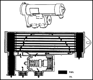
Figure 2.11. Fuel Oil-Cooler.
2.11. SUMMARY
The fuel system must supply clean, accurately metered fuel to the combustion chamber. Most turbine engine fuel systems have the same components: fuel control, pressure pumps, fuel flow divider, manifold, and atomizers. There are two types of fuel controls: hydromechanical and electronic. Engine-driven fuel pumps are high-pressure, positive-displacement, gear type pumps, and the fuel nozzles are either simplex or duplex. However, some engines use vaporizer tubes in place of fuel nozzles. Some gas turbine engines use a fuel oil-cooler to cool the oil.
Section II. Lubrication Systems
2.12. GENERAL
During the first few years of gas turbine experience, lightweight, petroleum-base oil was suitable for gas turbines as well as other types of engines. Most of the early engines used lubricating oil conforming to MIL-O-6081A, Grade 1010. Engines requiring an extremely light oil were operated on MIL-O-3519, Grade 1005. These were conventional petroleum oils of high quality and light weight which met the requirements of all the older engines.
Because of the continuous demand for greater power, gas turbine engines have been designed to operate at higher temperatures and pressure ratios. Some gas turbine engine oil temperatures encountered are considerably above the flash point of the petroleum oils. Because of this, a high temperature lubricant had to be developed. The oil used in all Army gas turbine engines is MIL-L-23699, or MIL-L-7808. These are synthetic lubricants which have wide operating ranges and load carrying capabilities. The MIL-L-7808 is used in engines operating below -25° F. OAT, and MIL-L-23699 is used when temperatures are above -25° F. This section discusses the various components that make up a typical lubricating system.
2.13. LUBRICATING SYSTEMS
Lubricating systems for modern gas-turbine engines are relatively simple in design and operation, but their function is of vital importance. The principal purposes of the lubricating system are to clean, reduce friction, and to cool the bearing surfaces. The main units of the typical system are the reservoir or oil tank, the pressure pump, scavenger pumps, filters, oil cooler, and spray oil jets. A schematic illustration of a gas turbine engine oil system is shown in figure 2.12.
Most gas turbine engines are of the dry-sump type, meaning the on is stored separately from the engine, or the tank may be attached to a structural part of the engine. Usually constructed of welded aluminum or steel, it can contain a venting system, a deaerator (baffles) to separate air from the oil. Some systems use an oil level transmitter to indicate quantity, where others have a dipstick or visual sight gage.
2.15. PRESSURE PUMPS
Oil pumps for turbine engines are usually of the positive-displacement gear type, with a relief valve to prevent excessive pressure. A modified gear-type pump is called the "gerotor pump."
The gear-type pump consists of a driving and driven gear. The pump is driven from the engine accessory section and causes the oil to pass around the outside of the gears in pockets formed by the gear teeth and the pump casing. The pressure developed is proportional to engine rpm up to the point where the pressure relief valve opens and limits the pressure output of the pump.
The gerotor pump has two moving parts, an inner toothed element meshing with an outer toothed element. The inner element has one less tooth than the outer, and the missing tooth provides a chamber to move the fluid from the intake to the discharge port. Both elements are mounted eccentrically to each other, the inner one mounted on the shaft and the outer one meshed with it. Figure 2.13 is a picture of the gerotor pump, showing both inner and outer toothed elements.
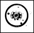
Figure 2.13. Gerotor Booster Pump.
Although much larger in total capacity, scavenge pumps are usually constructed in the same manner as pressure pumps. Engines are generally provided with several scavenge pumps to drain oil from various parts of the engine. Often such a pump shares the same housing as the pressure pump. These pumps are used to draw the oil from the sumps at the bearings, accessory gearbox housings, and other drainage points and return the oil back to the tank.
2.17. FILTERS
Three basic oil filters or strainers are made: cartridge, screen-disk, and screen. These filters are the same design as the filters used in the fuel system, as covered in paragraph 2.8. The main objective of a filter is to remove all foreign particles from the lubricant without creating excessive back pressure against the pumps. Filters are usually provided with bypass valves to permit the flow of oil in case the filter becomes clogged.
2.18. OIL COOLER
Oil coolers for aviation gas-turbine engines are either simple oil radiators with air cooling or the kind that uses fuel as the cooling medium. The latter type of unit is used on the Lycoming T55 engine. The fuel oil-cooling unit is a heat exchanger which transfers the heat in the oil to the fuel flowing to the fuel nozzles. Since the fuel flow through the cooler is much greater than the oil flow, the fuel is able to absorb a considerable amount of heat from the oil, thereby reducing the size and weight of the cooler. The fuel oil-cooler is shown in figure 2.11. An air cooler is shown in figure 2.14.
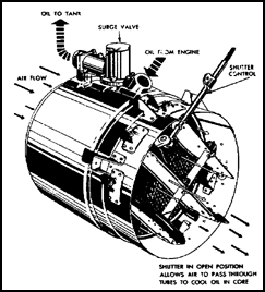
Figure 2.14. Air Oil Cooler.
2.19. SPRAY OIL JETS
The lubrication method most generally used is known as a calibrated system, where oil is specifically controlled by a calibrated orifice which provides the proper oil flow at all engine operating speeds. The oil is supplied from the oil pressure pump through tubing and internal passageways to the spray jets, where the oil is sprayed on the bearing surfaces.
2.20. SUMMARY
Gas turbine engine oil systems perform three major functions. They clean and reduce friction, and they cool and dissipate heat. They also clean the engine interior through the use of oil filters and strainers. Because much of the aircraft powerplant consists of moving parts, lubricants are needed to overcome friction caused by one metal surface sliding or rolling over another. Friction causes heating of parts, excessive wearing, and useless expenditure of horsepower. Lubricating systems used in gas turbine engines have oil tanks, pressure pumps, scavenger pumps, filter, oil coolers, and spray oil jets. The system most widely used on turbine engines is the dry sump lubrication system which uses a separate or external oil tank, located near the engine.
The two kinds of pumps are pressure pumps and scavenge pumps, the first to put oil into the system, and the second to collect oil from the system. Filters remove foreign matter from the oil, and either a fuel oil-cooler or an air cooler takes the heat out of it. Oil is sprayed on the bearing surface by spray jets.
Section III. Ignition Systems and Engine Instrumentation
2.21. GENERAL
Gas turbine ignition systems fall into three general types: first, the induction type, that produces high tension voltage by conventional induction coils; second, the capacitor type that causes ignition by means of high energy and very high temperature sparks produced by a condenser discharge; and a third type of ignition system, not widely adopted, that uses a glow plug.
Most ignition systems used on Army aircraft are of the high-energy capacitor type. This system has been accepted for gas turbine engines because it produces high voltage and an exceptionally hot spark, and the high voltage covers a large area.
The tachometer is one of the cockpit instruments described briefly in this section. Others are indicating systems for torque, engine oil pressure, engine oil temperature, exhaust gas temperature, and fuel pressure.
Usually, gas turbine engines are equipped with two or more igniter plugs; however, the smaller engines like the T63 have only one igniter plug, sometimes called the spark plug. Igniter plugs serve a purpose similar to the spark plug in a reciprocating engine, although operation of the ignition system and the igniter plugs is necessary only for a short period during the engine starting cycle. On many installations, ignition is initiated simultaneously with the starter. The ignition cycle takes place several times per second and continues to operate as long as the ignition switch is on.
The term "high energy" is used in the section to describe the capacitor type of ignition system. However, the amount of energy produced is very small. The intense spark is obtained by expending a small amount of electric energy in a very short time. Energy is the capacity for doing work. It can be expressed as the product of the electrical power and time. Gas turbine ignition systems are rated in joules. The joule is also an expression of electric energy, being equal to the amount of energy expended in one second by an electric current of one ampere through a resistance of one ohm. All other factors being equal, the temperature of the spark is determined by the power level reached. A high-temperature spark can result from increasing the energy level, or by shortening the duration of the spark. Increasing the energy level requires a heavier, more bulky ignition unit, since the energy delivered to the spark plug is only about 30 to 40 percent of the total energy stored in the capacitor. Also the higher the current flow, the higher the erosion rate on the igniter plug electrodes. Furthermore, much of the spark would be wasted, because ignition takes place in a matter of microseconds. In a capacitor discharge ignition system, most of the total energy available to the igniter plugs is dissipated in 10 to 100 microseconds, with up to 80, 000 watts with a spark duration of 50 microseconds. Figure 2.15 shows a wiring schematic of a typical ignition unit.

Figure 2.15. Wiring Schematic of Typical Ignition Unit.
|
WARNING: |
When working around the ignition unit of the engine, disconnect the input lead to the ignition exciter unit. Remove the igniter plugs from the combustion chamber and ground them to the engine. You do this to dissipate any charge that might be left in the exciter unit. Some ignition exciter units contain a very small amount of radioactive material (cesium-barium 137) and normally require no handling precautions. However, severely damaged units that have been broken open must be handled with forceps or gloves and disposed of in accordance with AR 755-15. |
2.23. IGNITERS
Gas turbine igniters come in many sizes and shapes depending upon the duty they will be subjected to. The electrodes of the plugs used with high-energy ignition systems must be able to accommodate a current of much higher energy than the electrodes of conventional spark plugs are capable of handling. Although the high-energy current causes more rapid igniter-electrode erosion than that encountered in reciprocating-engine spark plugs, this is not a major disadvantage, because of the relatively short time that the ignition system is in operation. Most igniter plugs used in turbine engines are of the annular-gap type, shown in figure 2.16.
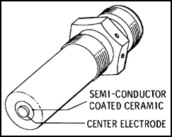
Figure 2.16. Annular Gap Igniter Plug.
The annular-gap igniter plug protrudes slightly into the combustion chamber liner to provide an effective spark. Another type of igniter is the constrained-gap plug which does not closely follow the face of the plug; instead it tends to jump in an arc which carries it beyond the face of the chamber liner. Because the constrained-gap plug does not have to protrude into the liner, the electrode operates at a cooler temperature than that of the annular-gap plug.
2.24. INTERNAL COOLING SYSTEM
The intense heat generated when combustion takes place means that all internal combustion engines must be cooled by some means. Air-cooled reciprocating engines are cooled by air passing over fins attached to the cylinders. Liquid-cooled engines, as in an automobile, use a liquid coolant that passes through jackets surrounding the cylinders. In a reciprocating engine, combustion takes place only during every fourth stroke of a four-cycle engine. However, in a gas turbine engine, where the burning process is continuous, nearly all the cooling air must pass through the inside of the engine. If only enough air were admitted to the engine to provide combustion, internal temperatures would increase to more than 4,000° F. Because of this, the amount of air admitted to the engine is in excess of the amount required for combustion only; indeed, about 75 percent of the air is used for cooling and 25 percent for combustion. This large surplus of air (secondary air) cools the hot expanding gases just before they enter the turbines. In some engines, internal air is bled from the engine compressor section and is vented through passages to the bearings and other parts of the engine. This air is then vented into the exhaust stream.
2.25. ENGINE INSTRUMENTATION
Engine performance is monitored by instruments mounted on the instrument panel in the cockpit.
![]() a. Tachometer system. The tachometer gives the pilot a continuous indication of engine rpm. A variety of systems or a combination of systems may be used on gas turbine engines. Gas producer or gas generator tachometers, turbine and rotor tachometers, and N1 and N2 tachometers are some of the tachometer systems used. The system may consist of dual indicators, registering rpm for multiengine aircraft, registering engine and rotor rpm for rotary-wing aircraft, or engine and propeller rpm for fixed-wing aircraft. A typical tachometer indicator is driven by a tachometer-generator. The generator supplies power at a frequency proportional to the driven speed which drives the synchronous motors in the indicator.
a. Tachometer system. The tachometer gives the pilot a continuous indication of engine rpm. A variety of systems or a combination of systems may be used on gas turbine engines. Gas producer or gas generator tachometers, turbine and rotor tachometers, and N1 and N2 tachometers are some of the tachometer systems used. The system may consist of dual indicators, registering rpm for multiengine aircraft, registering engine and rotor rpm for rotary-wing aircraft, or engine and propeller rpm for fixed-wing aircraft. A typical tachometer indicator is driven by a tachometer-generator. The generator supplies power at a frequency proportional to the driven speed which drives the synchronous motors in the indicator.
![]() b. Torquemeter indicating system. Sometimes called a torque pressure indicating system, the typical torquemeter indicating system is a pressure indicator for continuous readings of engine output-shaft torque. It is powered by an electrical transmitter mounted on the engine inlet section.
b. Torquemeter indicating system. Sometimes called a torque pressure indicating system, the typical torquemeter indicating system is a pressure indicator for continuous readings of engine output-shaft torque. It is powered by an electrical transmitter mounted on the engine inlet section.
![]() c. Engine oil pressure indicating system. A typical engine oil pressure indicating system gives continuous readings of engine oil pump pressure in psi to the indicator, by means of an electrical transmitter mounted on the engine inlet section. The transmitter is connected to the 28-volt ac electrical system, and by a hose to a pressure tap on the engine oil filter housing.
c. Engine oil pressure indicating system. A typical engine oil pressure indicating system gives continuous readings of engine oil pump pressure in psi to the indicator, by means of an electrical transmitter mounted on the engine inlet section. The transmitter is connected to the 28-volt ac electrical system, and by a hose to a pressure tap on the engine oil filter housing.
![]() d. Engine oil temperature indicating system. In a typical engine oil temperature indicating system, the indicator is electrically connected to the 28-volt dc system. An electrical resistance type thermobulb installed in the engine oil pump housing measures temperatures of the oil entering that unit. The temperature readings are transmitted to the indicator in degrees centigrade.
d. Engine oil temperature indicating system. In a typical engine oil temperature indicating system, the indicator is electrically connected to the 28-volt dc system. An electrical resistance type thermobulb installed in the engine oil pump housing measures temperatures of the oil entering that unit. The temperature readings are transmitted to the indicator in degrees centigrade.
![]() e. Exhaust gas temperature indicating system. The indicator in a typical exhaust gas temperature indicating system operates on electrical potential from an engine thermocouple harness with probes mounted in the aft section of the engine exhaust diffuser. The thermocouple is a device which converts heat into electricity. The exhaust gas temperature indicator (thermocouple thermometer indicator) is actually a sensitive millivoltmeter, calibrated in degrees centigrade. Its D'Arsonval movement is activated by an electrical force generated by its related thermocouple. The indicator circuit is entirely independent of any other electrical power source, and includes a coil resistor which provides a means of systems calibration.
e. Exhaust gas temperature indicating system. The indicator in a typical exhaust gas temperature indicating system operates on electrical potential from an engine thermocouple harness with probes mounted in the aft section of the engine exhaust diffuser. The thermocouple is a device which converts heat into electricity. The exhaust gas temperature indicator (thermocouple thermometer indicator) is actually a sensitive millivoltmeter, calibrated in degrees centigrade. Its D'Arsonval movement is activated by an electrical force generated by its related thermocouple. The indicator circuit is entirely independent of any other electrical power source, and includes a coil resistor which provides a means of systems calibration.
![]() f. Fuel pressure indicating system. A typical fuel pressure indicating system gives continuous readings of fuel pressure(psi) in the main fuel supply line from the boost pumps in the tanks, by means of an electrical transmitter. The transmitter is connected to a tap on the valve manifold where all the fuel supply lines join to deliver fuel to the engine through the fuel control inlet hose. Electricity is supplied to the transmitter by the 28-volt ac system.
f. Fuel pressure indicating system. A typical fuel pressure indicating system gives continuous readings of fuel pressure(psi) in the main fuel supply line from the boost pumps in the tanks, by means of an electrical transmitter. The transmitter is connected to a tap on the valve manifold where all the fuel supply lines join to deliver fuel to the engine through the fuel control inlet hose. Electricity is supplied to the transmitter by the 28-volt ac system.
2.26. SUMMARY
The three types of ignition systems used on turbine engines are induction, capacitor discharge, and glow plug. The most common ignition system used on Army aircraft is the capacitor discharge. The induction and capacitor systems use a spark producing plug to ignite the fuel air mixture.
Because of the high operating temperatures of turbine engines, an internal cooling system is used. Cooling air forms a blanket of air around the combustion chamber.
Instrumentation consists of tachometers, torquemeters, and pressure and temperature gages for monitoring engine performance.
GO TO: